
At Structured Design & Consulting, some of our most interesting projects start where straightforward design ends: limited access, existing structures that have to remain in service, incomplete subsurface information, and field conditions that don't allow a clean remove-and-replace solution.
The building sits in a small historic downtown in western Ohio, along a Main Street corridor where 19th-century commercial buildings back up directly onto grade-separated lots. The original sheet pile wall had been in the ground since before SD&C was involved in the project, quietly doing its job until age and corrosion caught up with it. A recent stretch of severe regional storms only reinforced the timeline: growing signs of distress made clear that a permanent solution couldn't wait for a more convenient season.
Site Photographs Before Repairs:
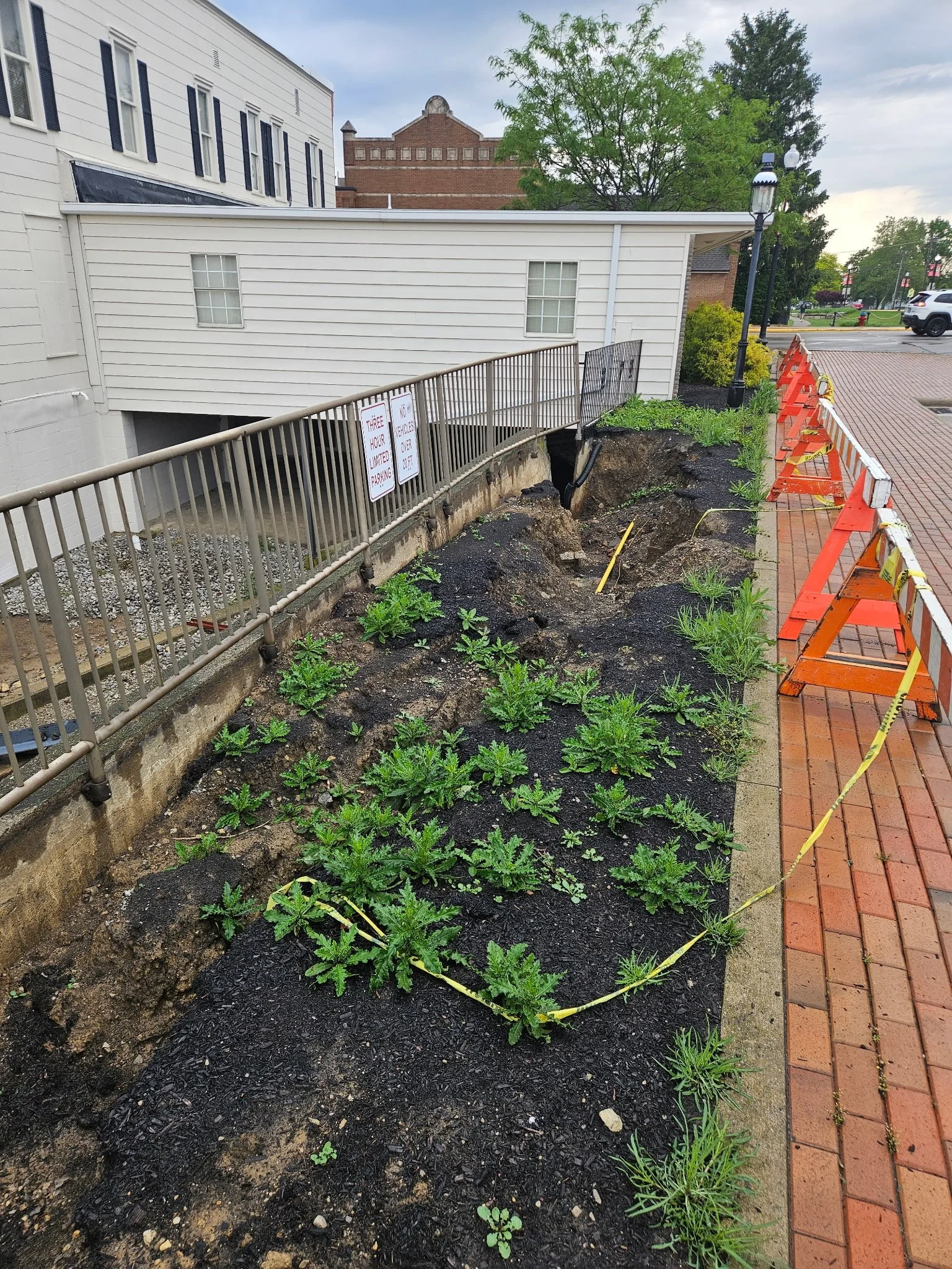
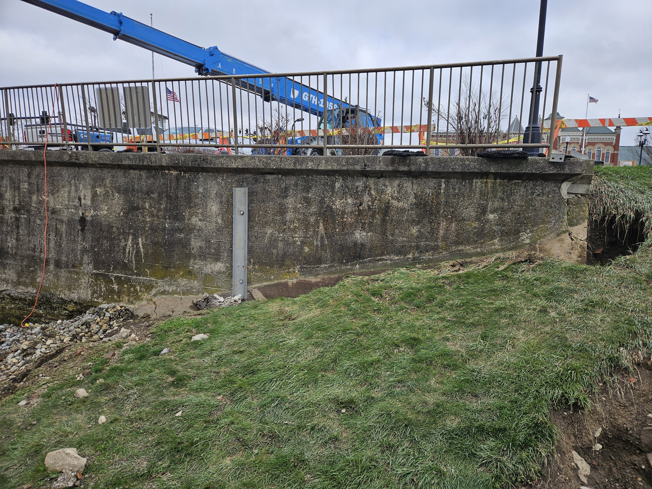
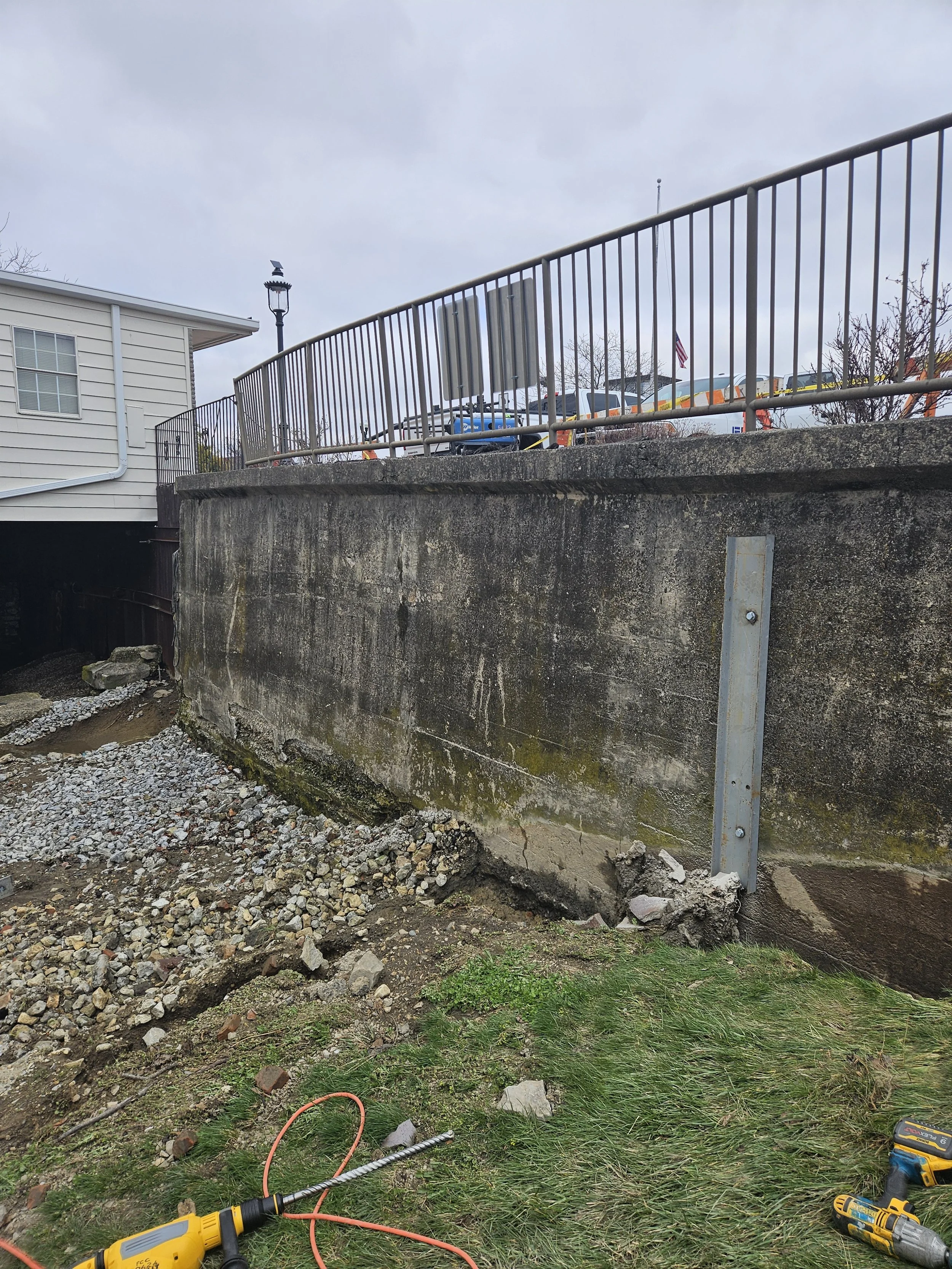
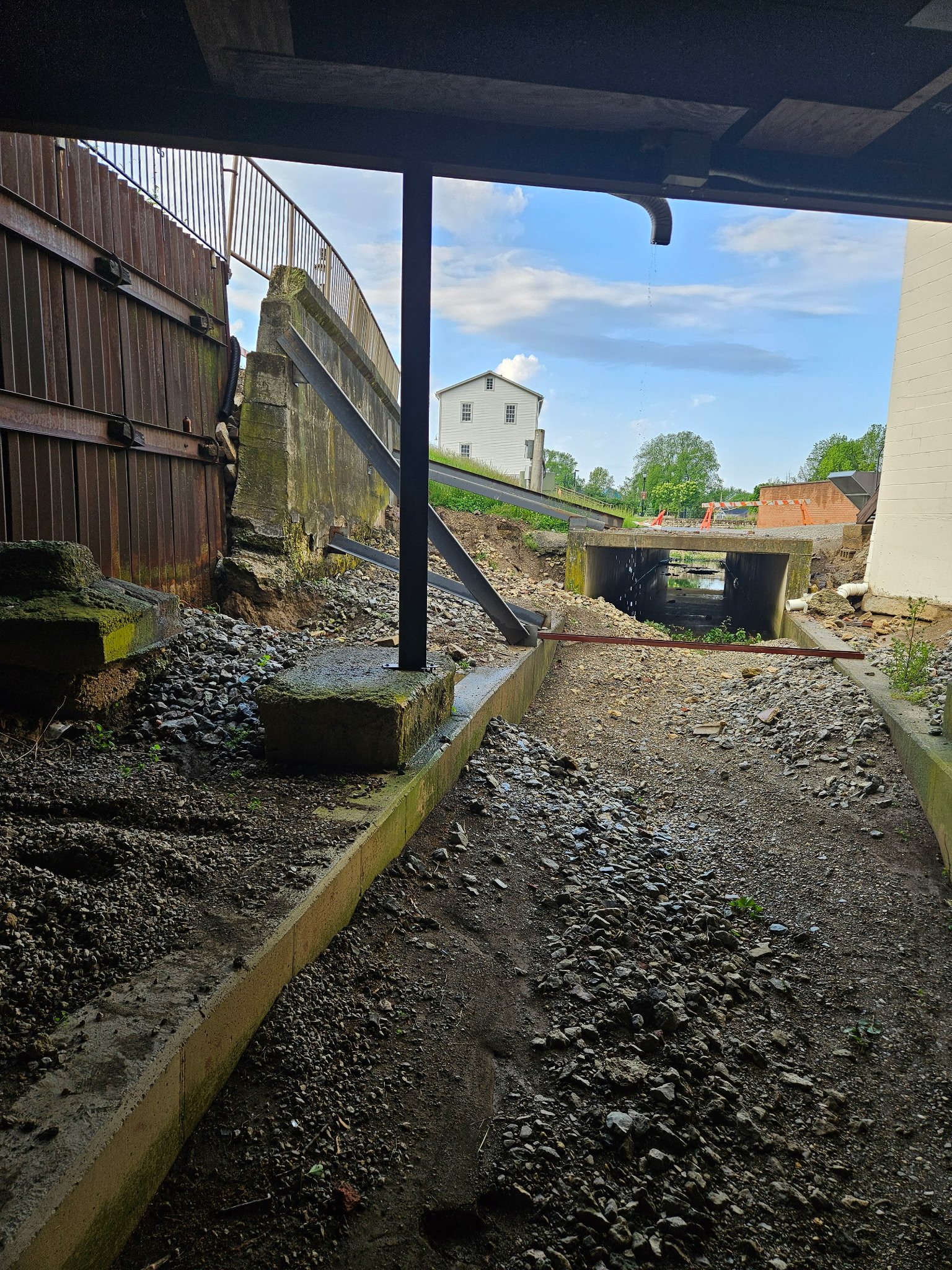
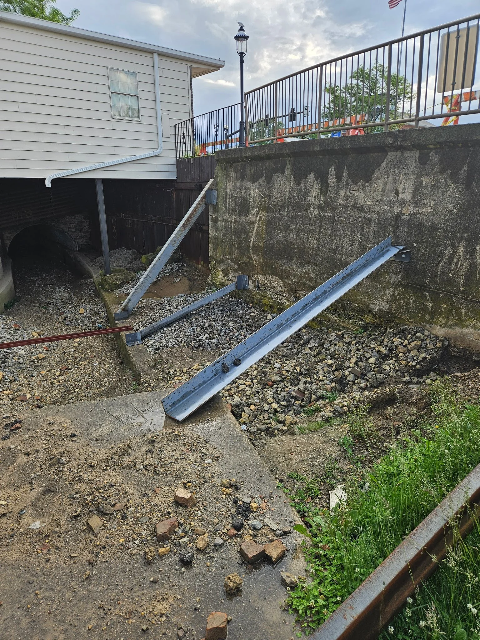
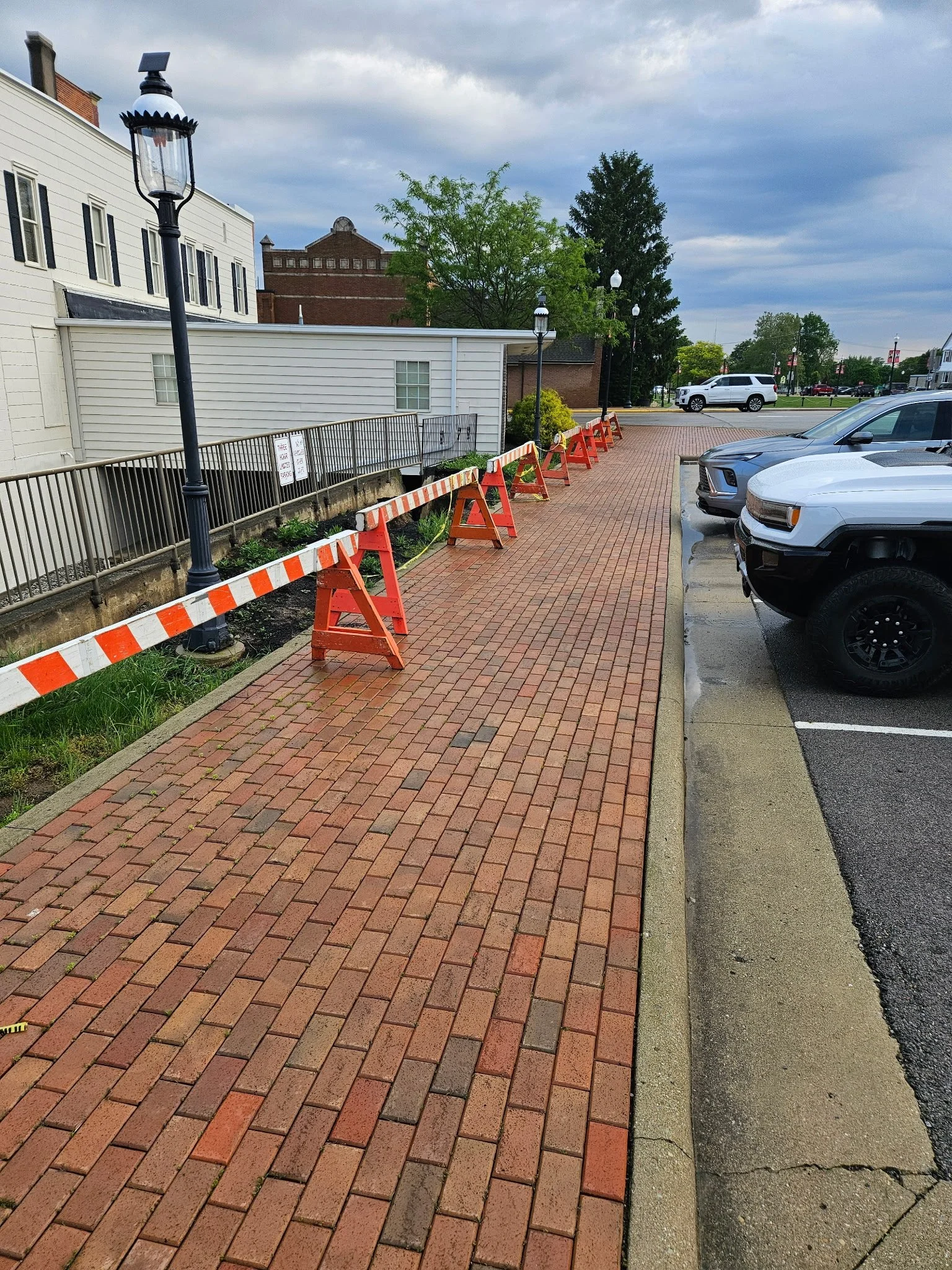
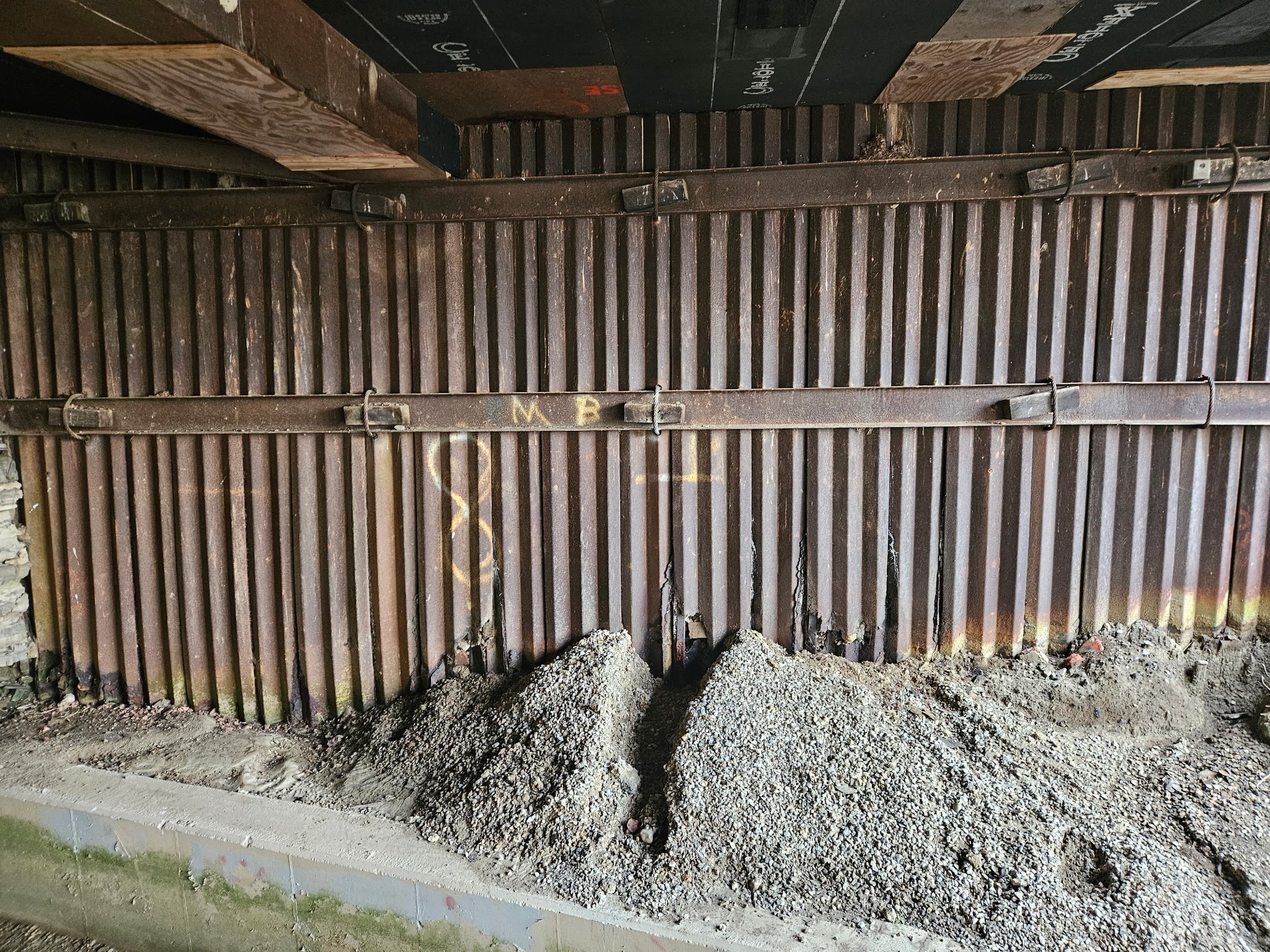
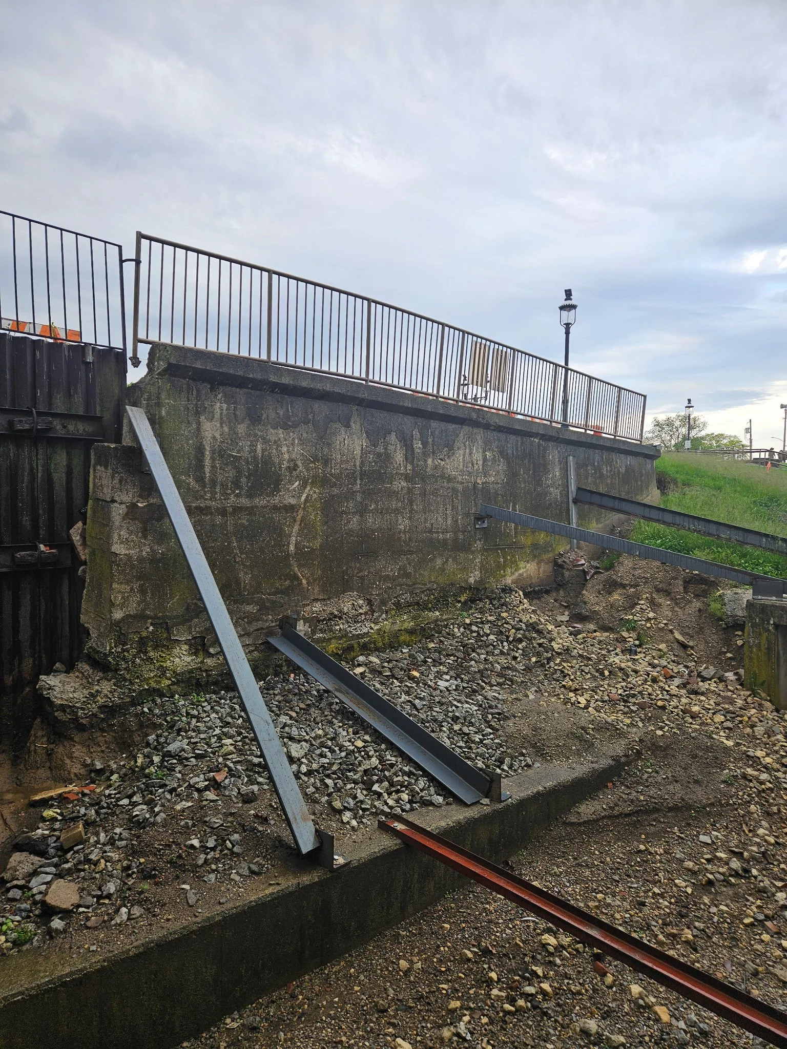
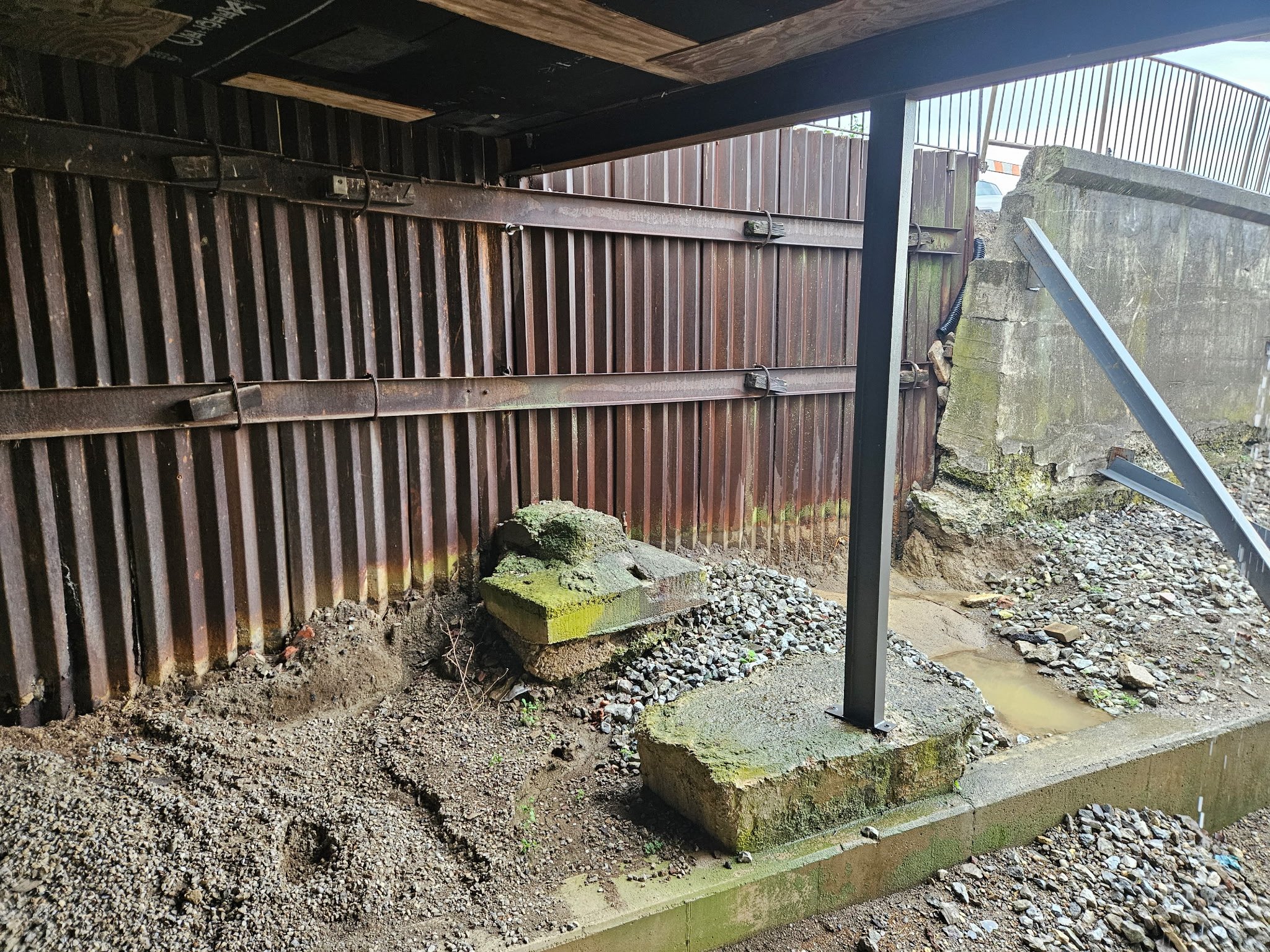
Earlier this year, Dax Clapsaddle, P.E., led the design of a permanent earth retention wall in a small Midwestern town’s historic downtown. The wall sits directly beneath and alongside a century-old building that now houses part of an active manufacturing operation. For decades, an aging steel sheet pile wall had quietly held back the soil behind that building. It was finally showing its age: corroded, distorted, and no longer something anyone wanted to trust with an occupied structure sitting on the ground behind it.
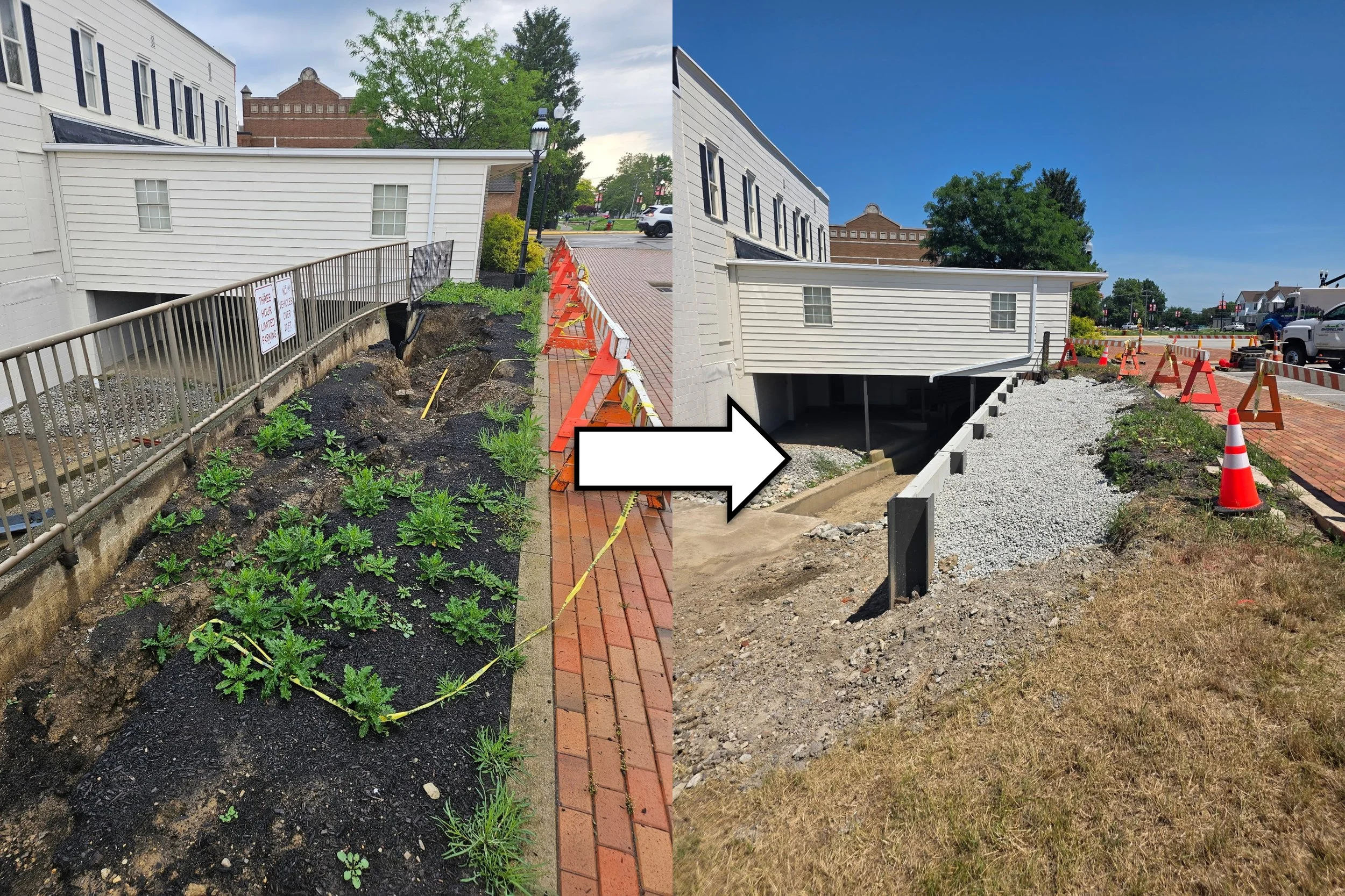
The Situation
The wall sat directly under and alongside an occupied building. That created a short list of hard constraints that shaped the entire design:
Tight footprint. No room existed to pull the old sheet piling and start fresh.
Had to tie in. Whatever replaced the old wall needed to connect to what was already there, not remove and replace it.
Minimize disruption. The replacement system needed to be constructed without adversely affecting the occupied structure above and adjacent to the wall.
Built for the long haul. This was never temporary shoring to get through a construction phase; it was designed from day one as a permanent earth-retention system, not temporary construction shoring.
Designing Around Limited Subsurface Information
Every retaining wall design starts with knowing what’s in the ground, and this one didn’t have the luxury of a dedicated investigation. The best available information was a subsurface exploration report from 2013, originally drilled for an addition to the same Opera House building, plus soil borings pulled from a nearby parking lot project down the street.
That’s usable information, but it isn’t the same as borings drilled at the wall itself. When subsurface information is limited, you have to recognize those limitations and account for them appropriately in the design. So, the engineering leaned conservative throughout: no reliance on passive soil resistance near the base of the piles, steel stress capped at two-thirds of yield, and a drainage system designed to relieve water pressure and reduce the potential for hydrostatic pressure developing behind the wall. Whatever the old borings couldn’t confirm, the design margin had to cover.
What the design leaned on, since site-specific borings weren't available
- Active lateral earth pressure factor of 1.0, no reduction for favorable conditions
- Passive soil resistance near the base of the piles: not relied on
- Steel stress capped at two-thirds of yield
- Granular, free-draining backfill required behind the entire wall
- No reliance on future erosion or scour protection unless separately addressed
- The design required field conditions encountered during construction to be compared with the assumed conditions, with significant discrepancies reported to SD&C for evaluation
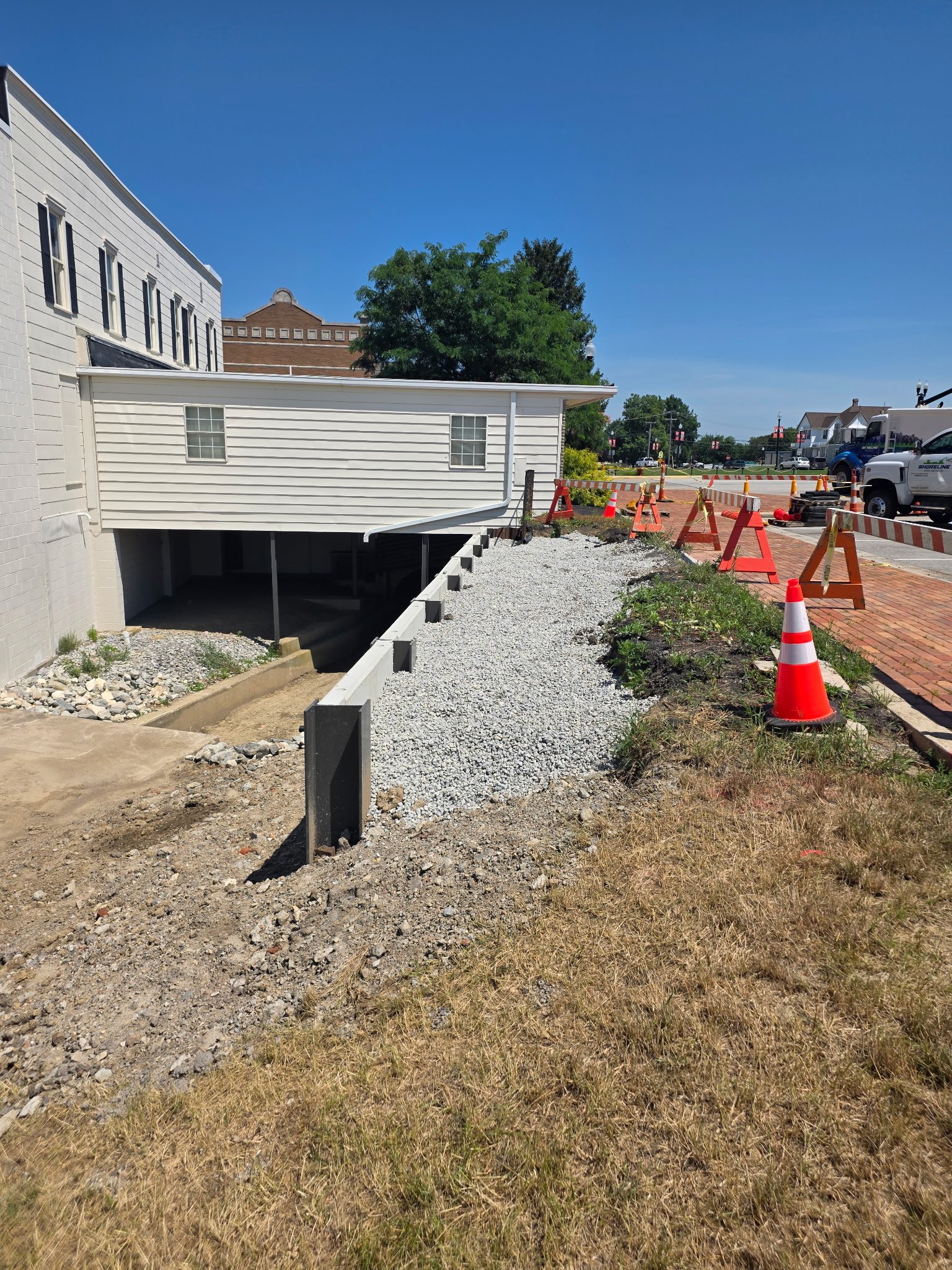
The Design
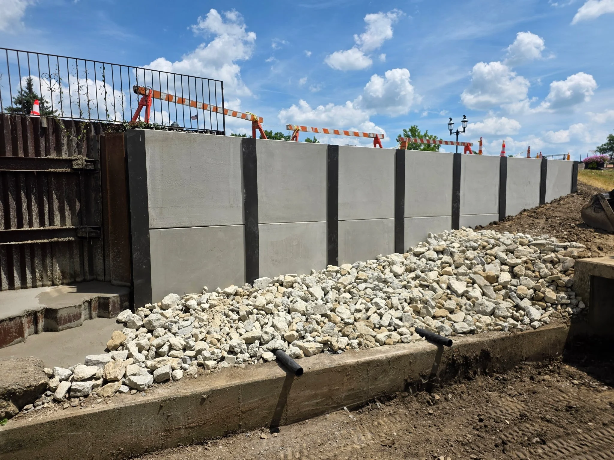
Several configurations were studied before landing on the final geometry, from cantilevered sheet piles to tied-back soldier piles at retained heights ranging from 5 feet to nearly 10 feet. What went in the ground is a permanent soldier pile and concrete lagging wall: nine HP12×53 steel piles set into 21-inch diameter drilled shafts, spaced roughly 6 feet apart across a 49-foot run. The wall steps down as it goes, from a 9-foot 6-inch retained height at the tall end to just 3-foot 6-inch at the low end, following the grade back down toward the street.
Six-inch precast concrete lagging panels span between the piles, backed by free-draining gravel and 2-inch weep holes spaced every 4 feet to provide a drainage path and reduce the potential for water pressure to develop behind the wall. The piles are painted with a coating system rated for long-term exposure, since a wall like this doesn’t get a second chance at corrosion protection once it’s buried.
Tying Old to New
The trickiest detail wasn’t the new wall itself, it was the connection back to the sheet piling that remained in place. About 3 feet of the existing wall was retained and lapped into the new system using an SKS11 sheet pile interlock.
Because the condition of the existing steel below grade could not be fully confirmed before construction, the design did not assume ideal conditions. Instead, the connection detail and adjacent new wall system were developed to account for that uncertainty while minimizing reliance on the existing wall to the extent practical.
The Takeaway
Existing-condition projects rarely come with perfect information. Access is limited, existing construction may not be fully documented, subsurface information may be incomplete, and the structure above still has to remain in service.
That is where engineering judgment becomes especially important.
For this project, the solution wasn't simply to replace an old wall. It was to understand what could remain, identify where uncertainty existed, make appropriate conservative assumptions, and develop a permanent earth-retention system that could actually be built within the constraints of the site.
At Structured Design & Consulting, this is the type of construction engineering work we enjoy most: solving difficult earth-retention, temporary-works, and structural problems where constructability matters just as much as the calculations.