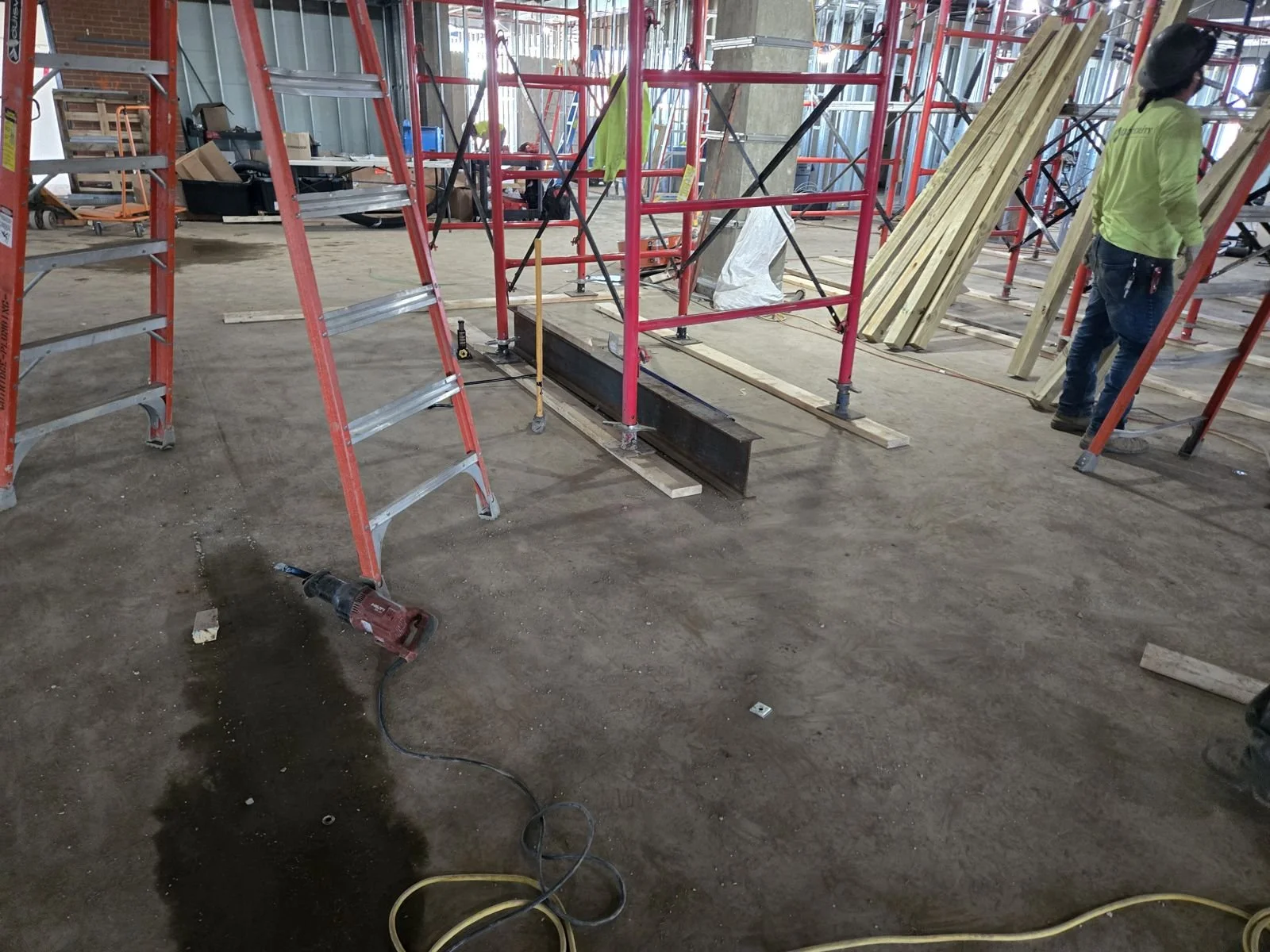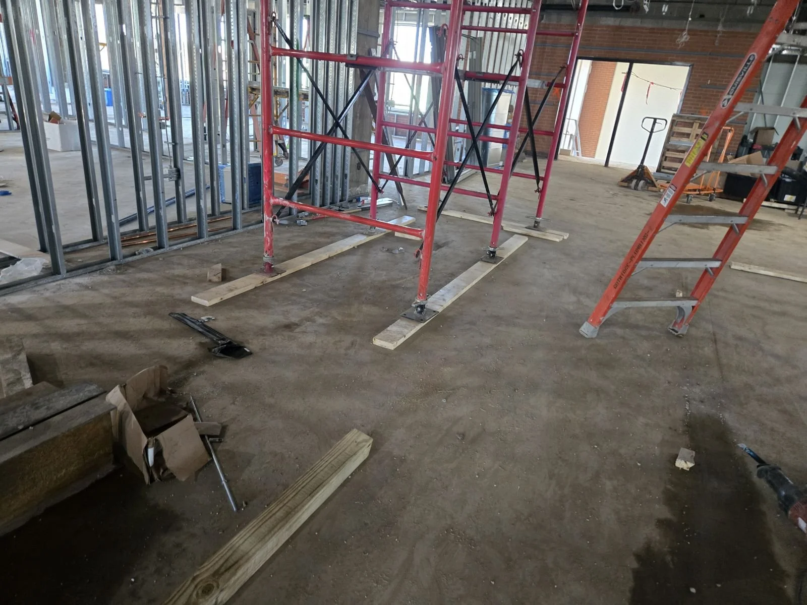
Keeping the Work Moving: Coordinated Shoring for a University Library Renovation

Temporary shoring has to do more than carry load. It must fit the building, the available equipment, and the work sequence.

At a university library, crews needed to create elevator and mechanical shaft openings through an existing concrete pan-deck floor. The floor had to remain supported during demolition and new concrete beam work, while the shoring fit around existing framing and left room for crews to work below.

SD&C was initially brought in to help with the demolition shoring. As planning moved forward, the concrete contractor also needed shoring to install the new concrete beams. SD&C already had an established working relationship with that contractor, and the project included an additional shoring phase for the concrete work. As time was of the essence, it made sense for SD&C to stay involved across both phases and coordinate the floor support as one staged effort.
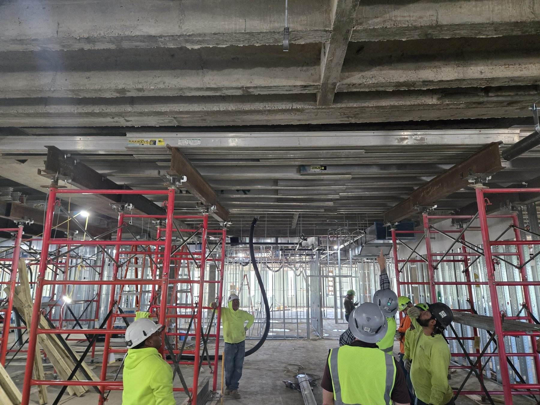
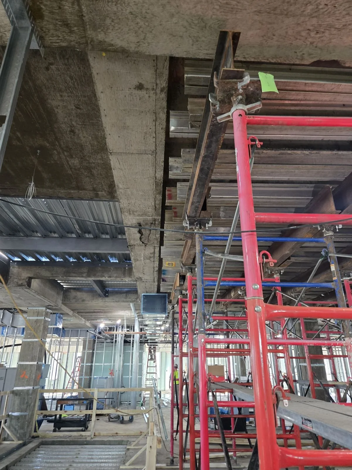
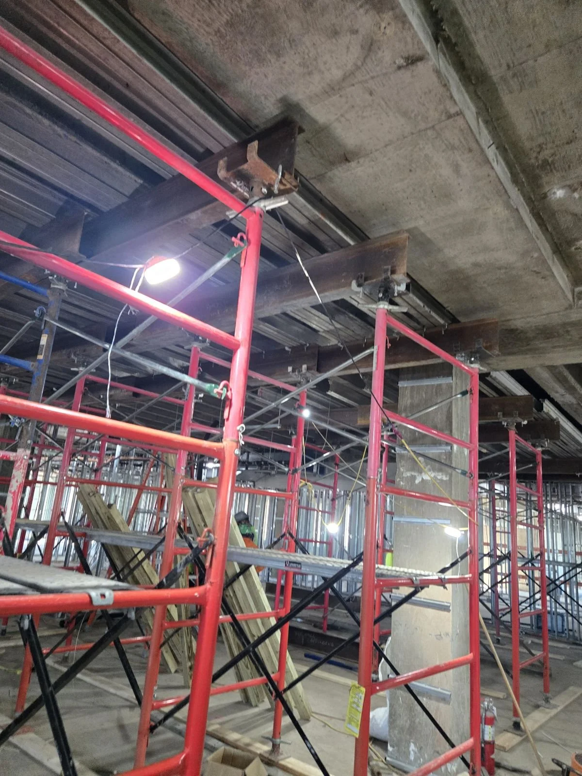
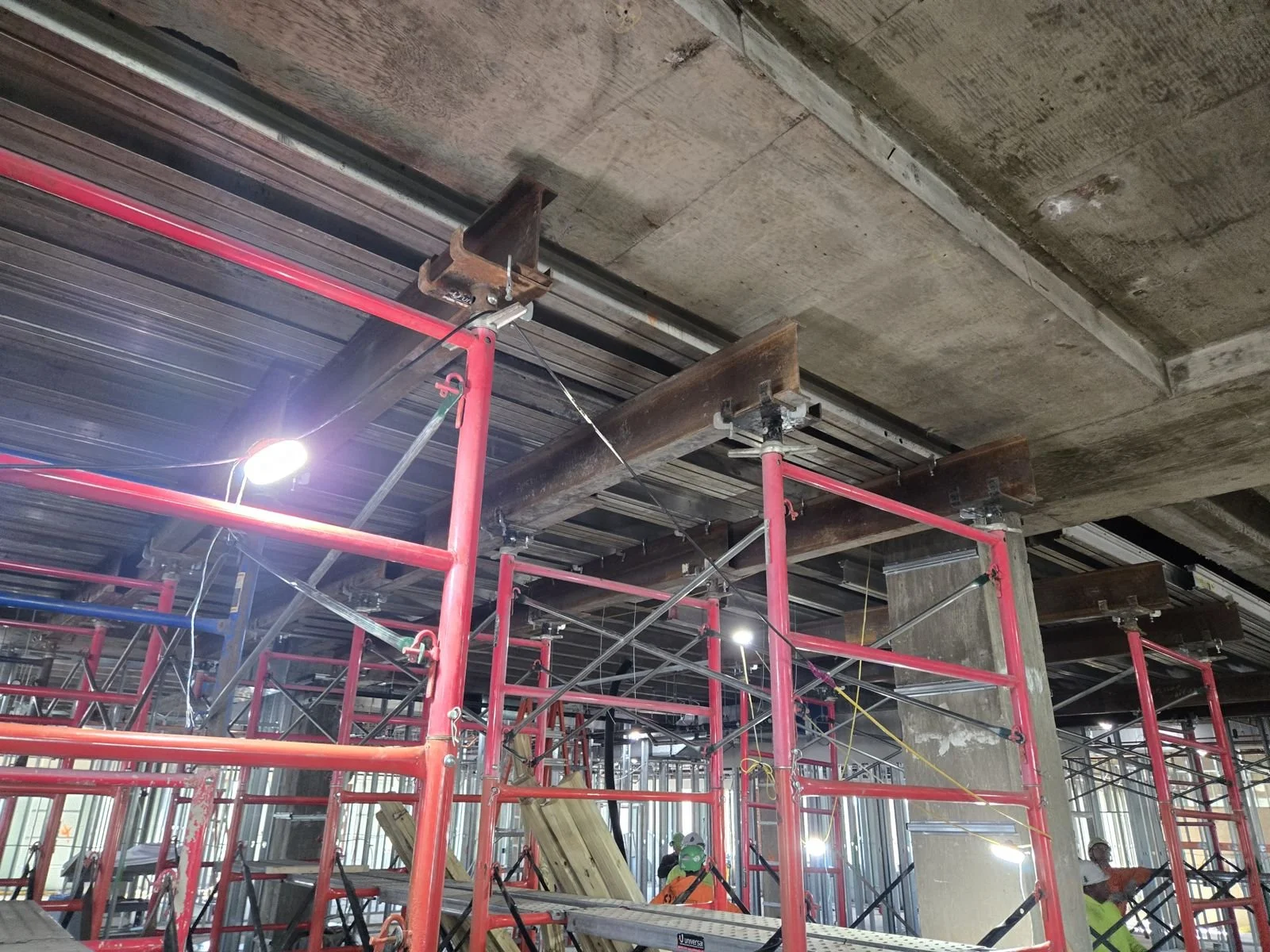
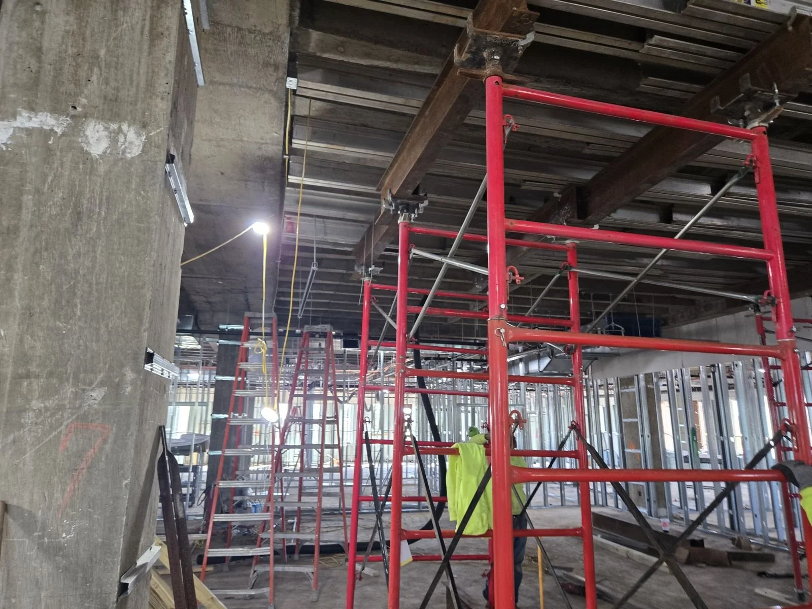
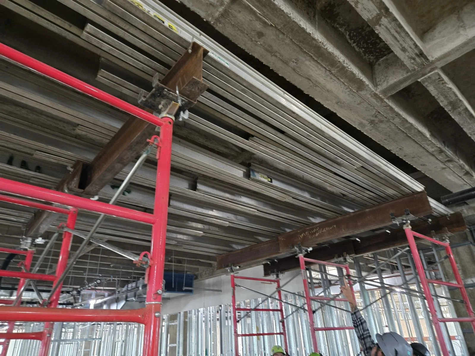
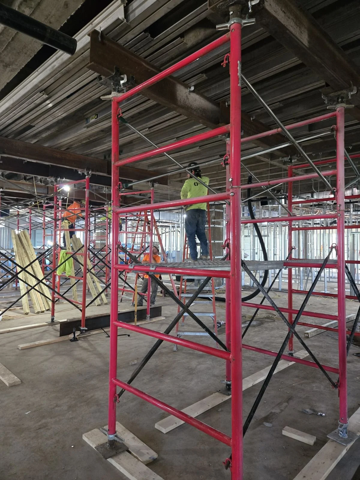
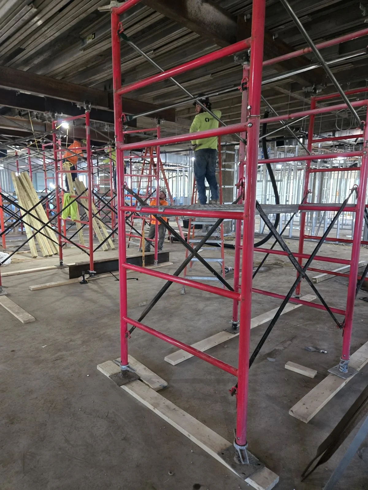
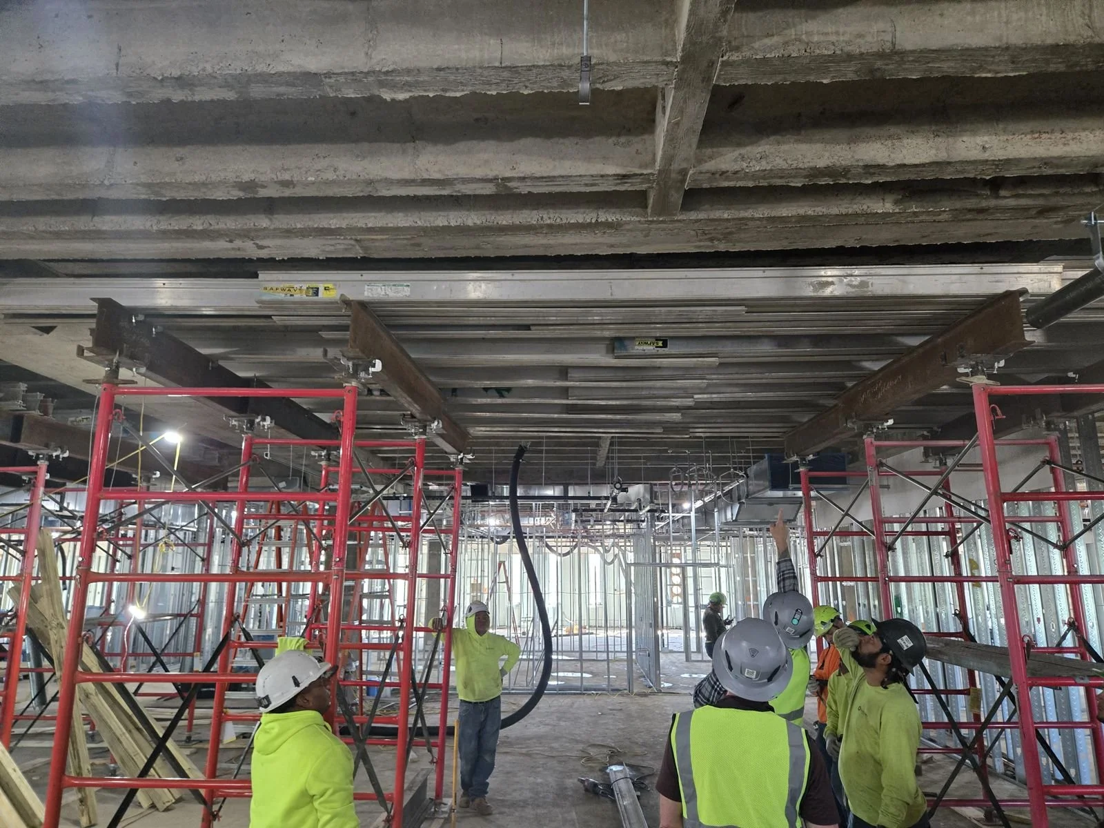
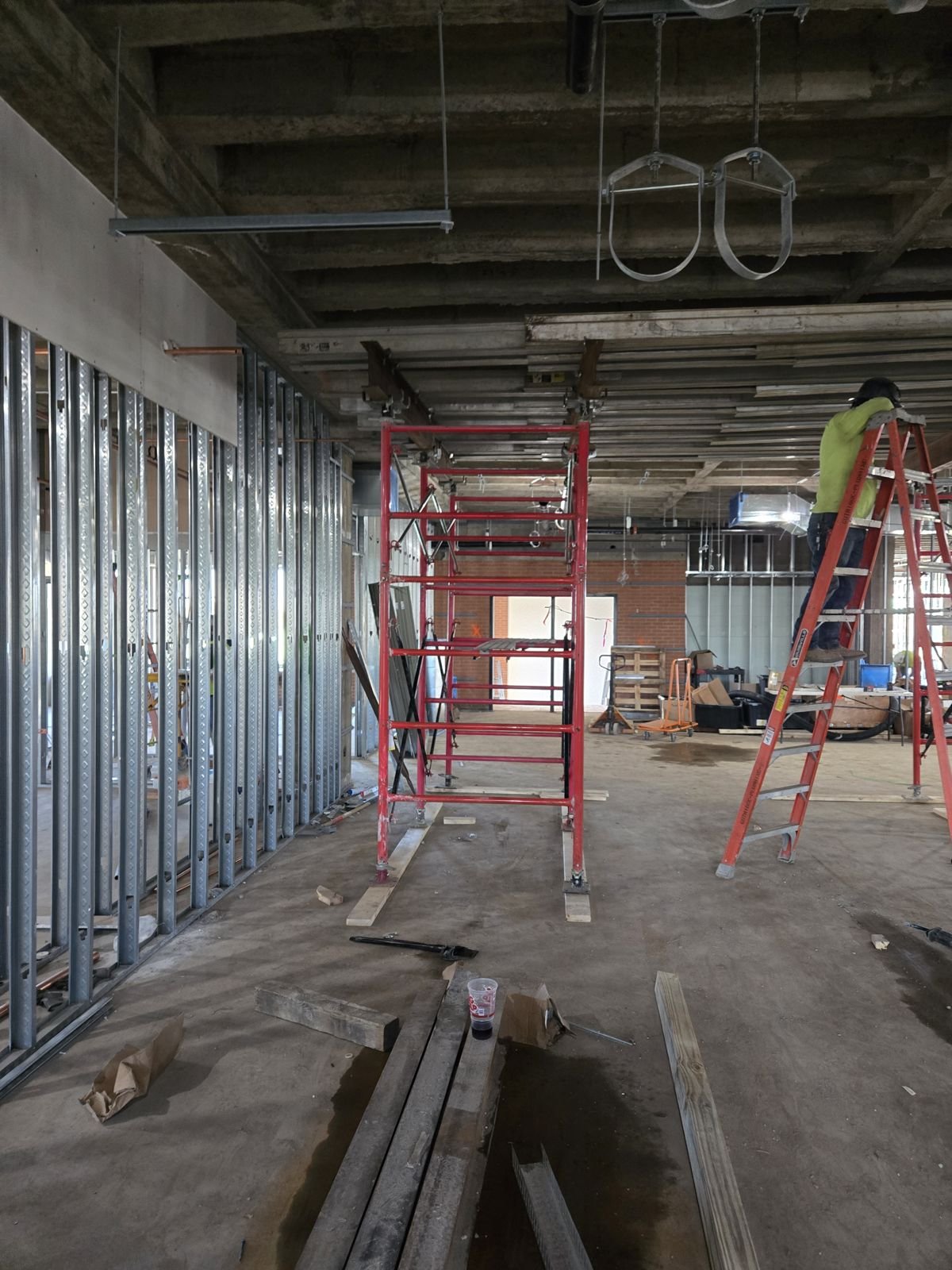
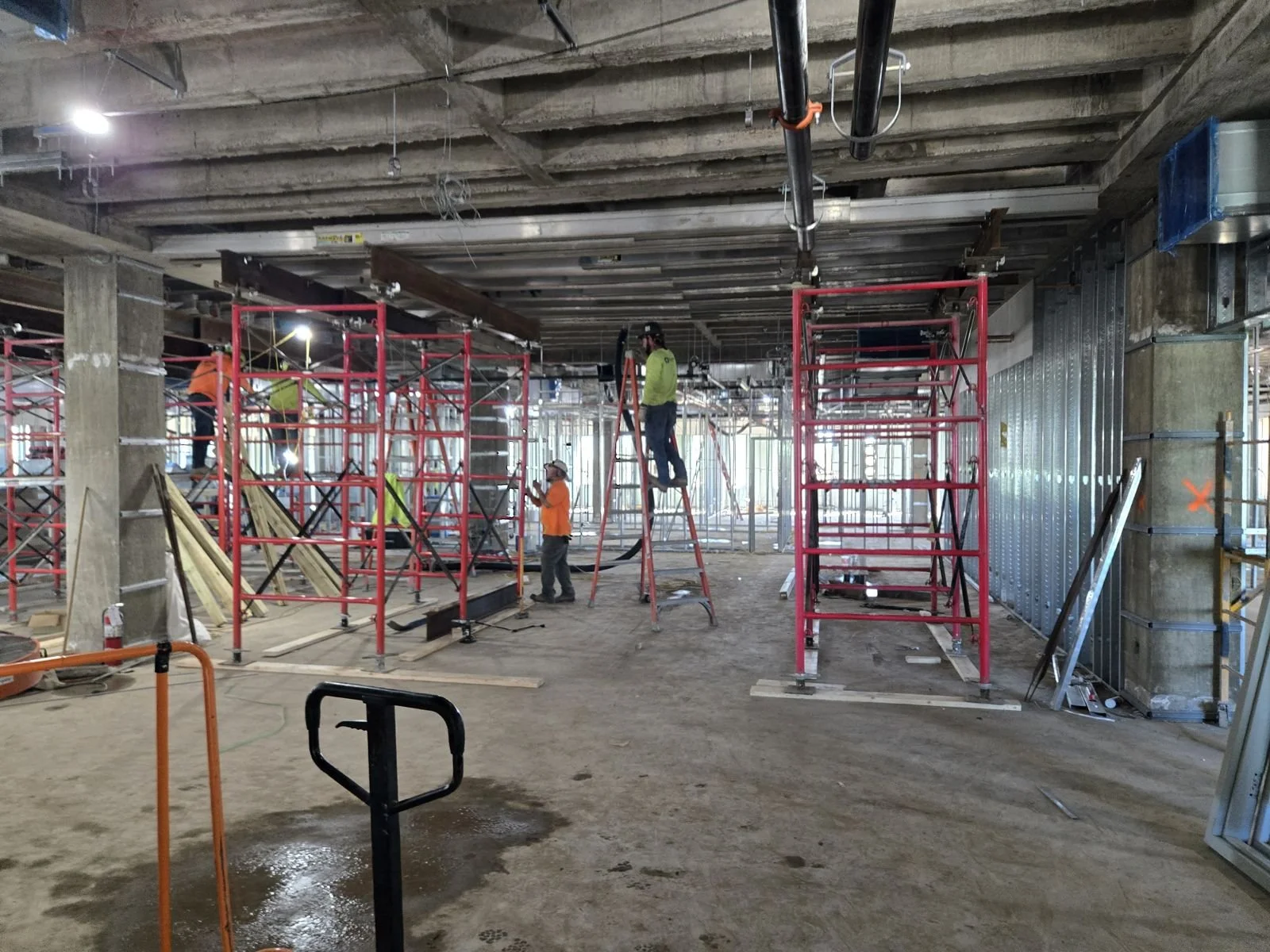
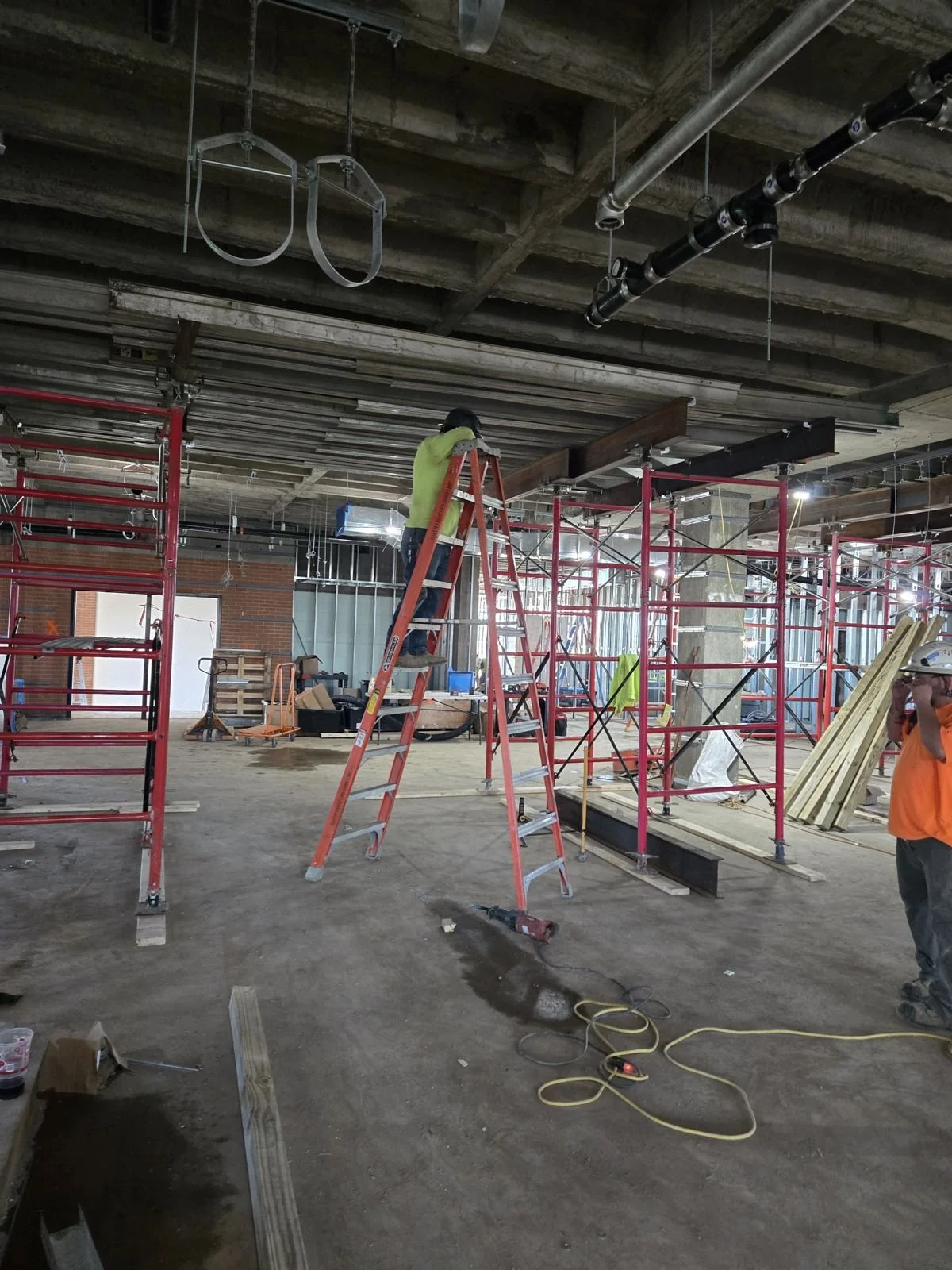
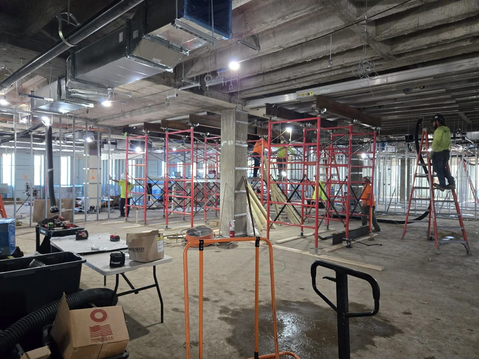
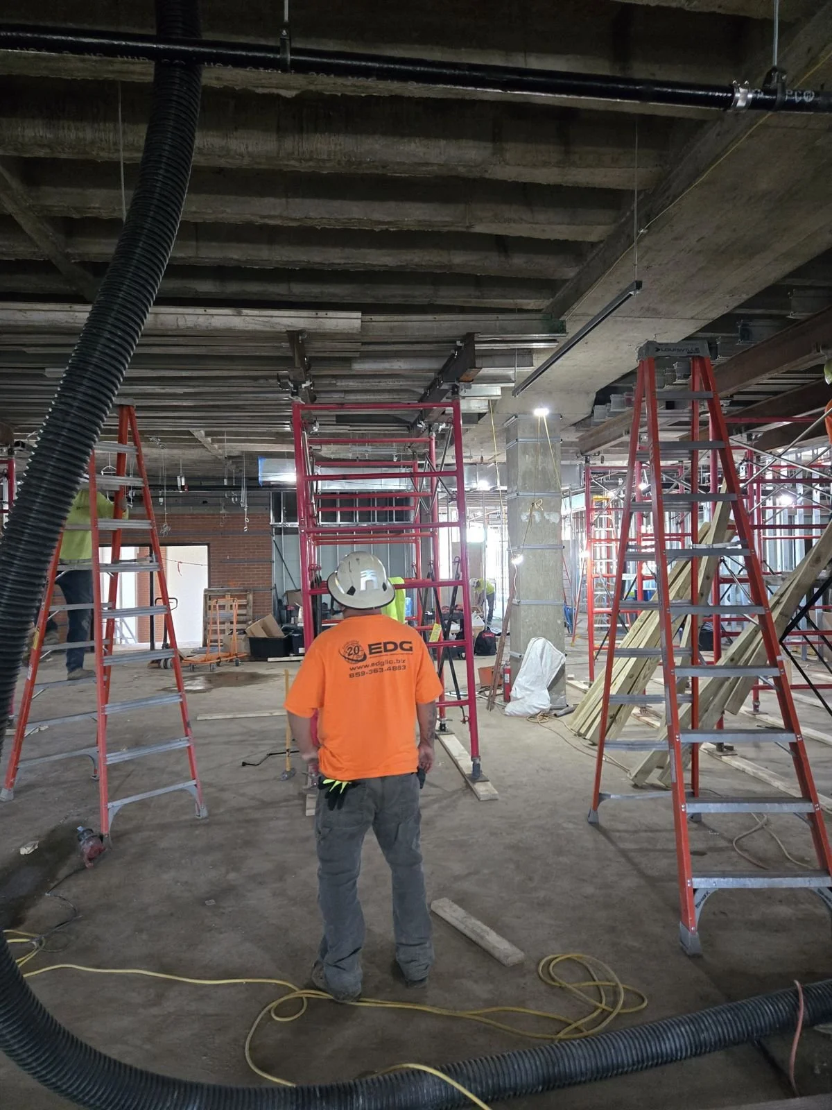
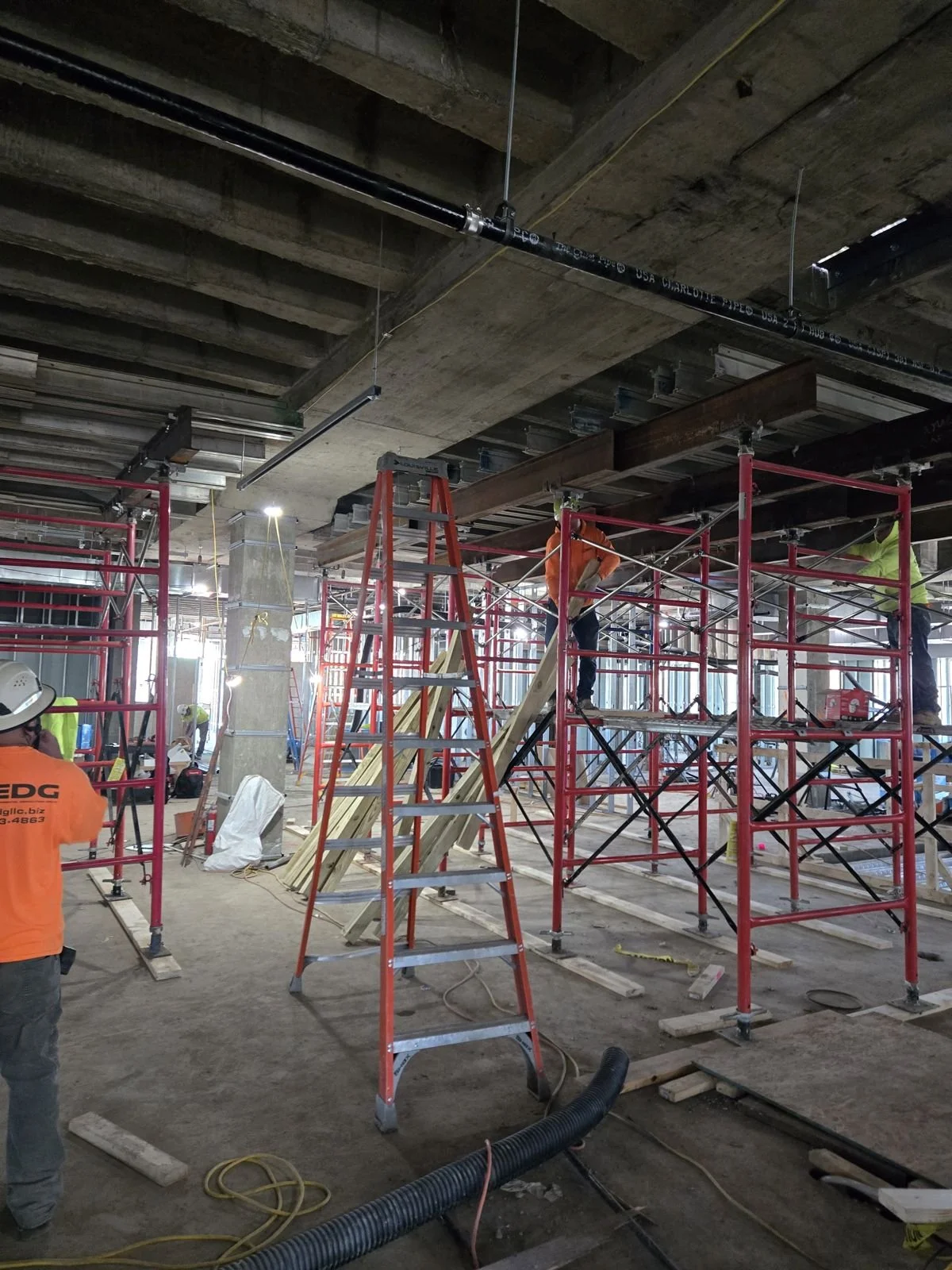
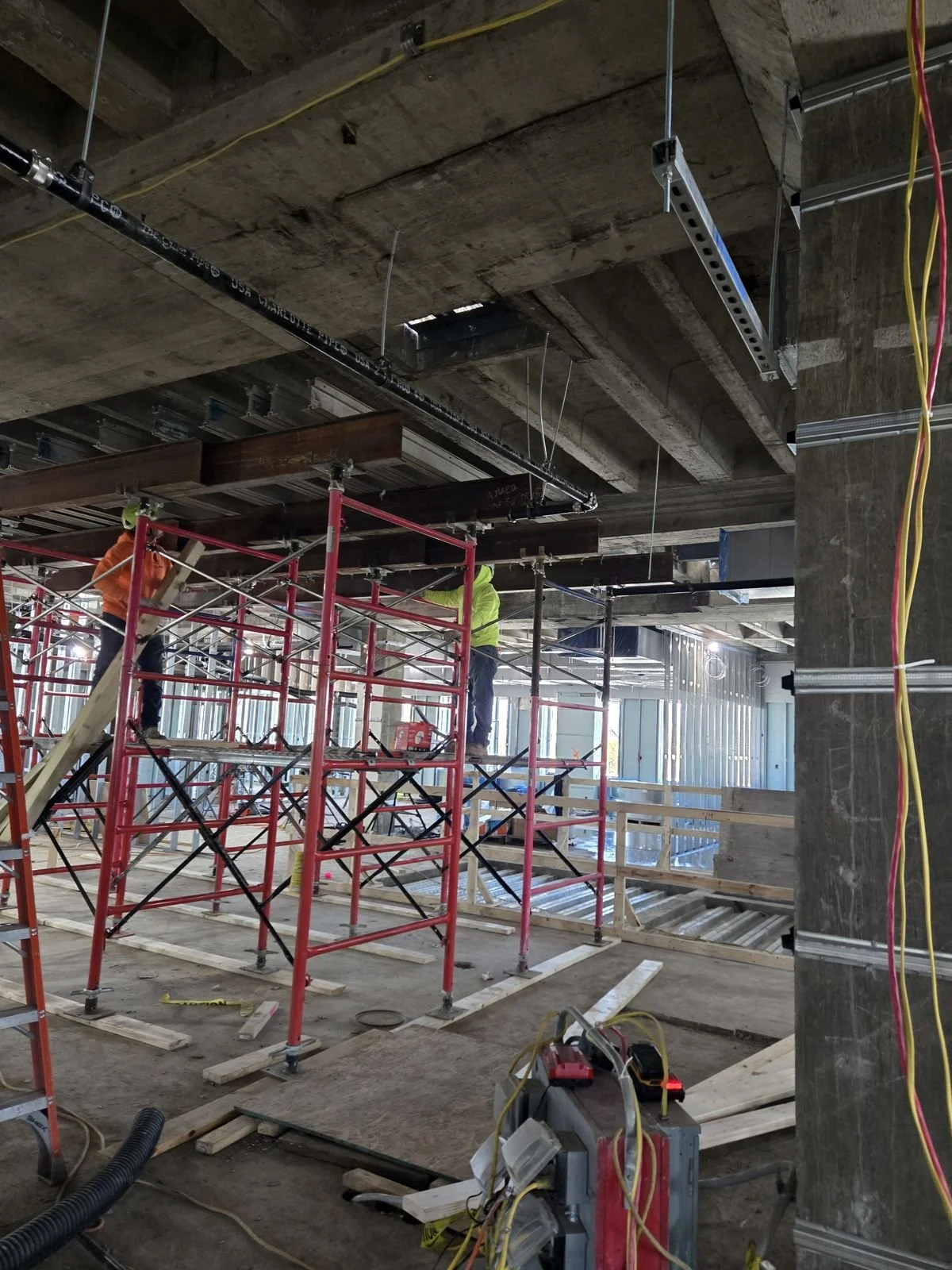
Steel beams bearing on scaffold towers to support the remaining deck.

The Situation

The floor framing plans identified two types of openings on 4 different levels:

  • Elevator shaft opening, requiring demolition of existing concrete joists.

  • Mechanical shaft openings, also requiring demolition of existing concrete joists.

The planned work included one Elevator Shaft opening and two Mechanical shaft openings at each floor. Shoring was planned in two-floor stages. After the new concrete beams were installed and cured, the team could move the equipment to the remaining floors.

150 PSFDesign floor load: 100 psf dead + 50 psf construction live
2 LOAD CASESanalyzed for each modeled opening
4 FLOORS2 floors at a time in two phases in the planned shoring sequence
3 OPENINGSper floor: one elevator opening and two mechanical openings

Designing for Changing Conditions

The shoring design considered two construction conditions at each opening:

  • Existing-joist demolition: the area being demolished, the tributary floor area remaining and temporarily supported, and construction live load.

  • New-beam placement: the weight of the proposed beam, the tributary floor area remaining and temporarily supported, and construction live load.

The calculated dead load was 100 psf. A 50 psf construction live load brought the total design floor load to 150 psf. The analysis also included the dead load of the proposed concrete beams at the openings.

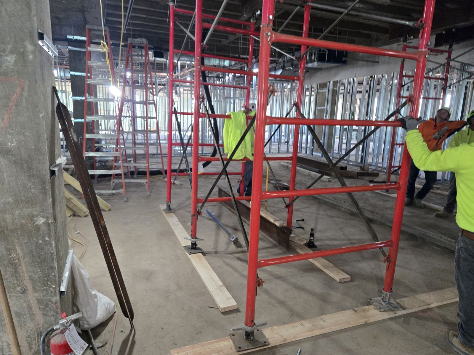
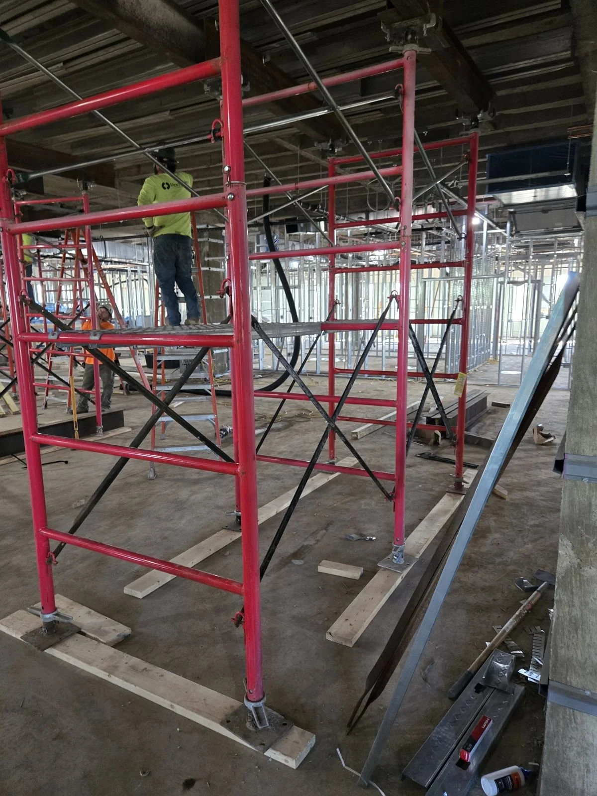
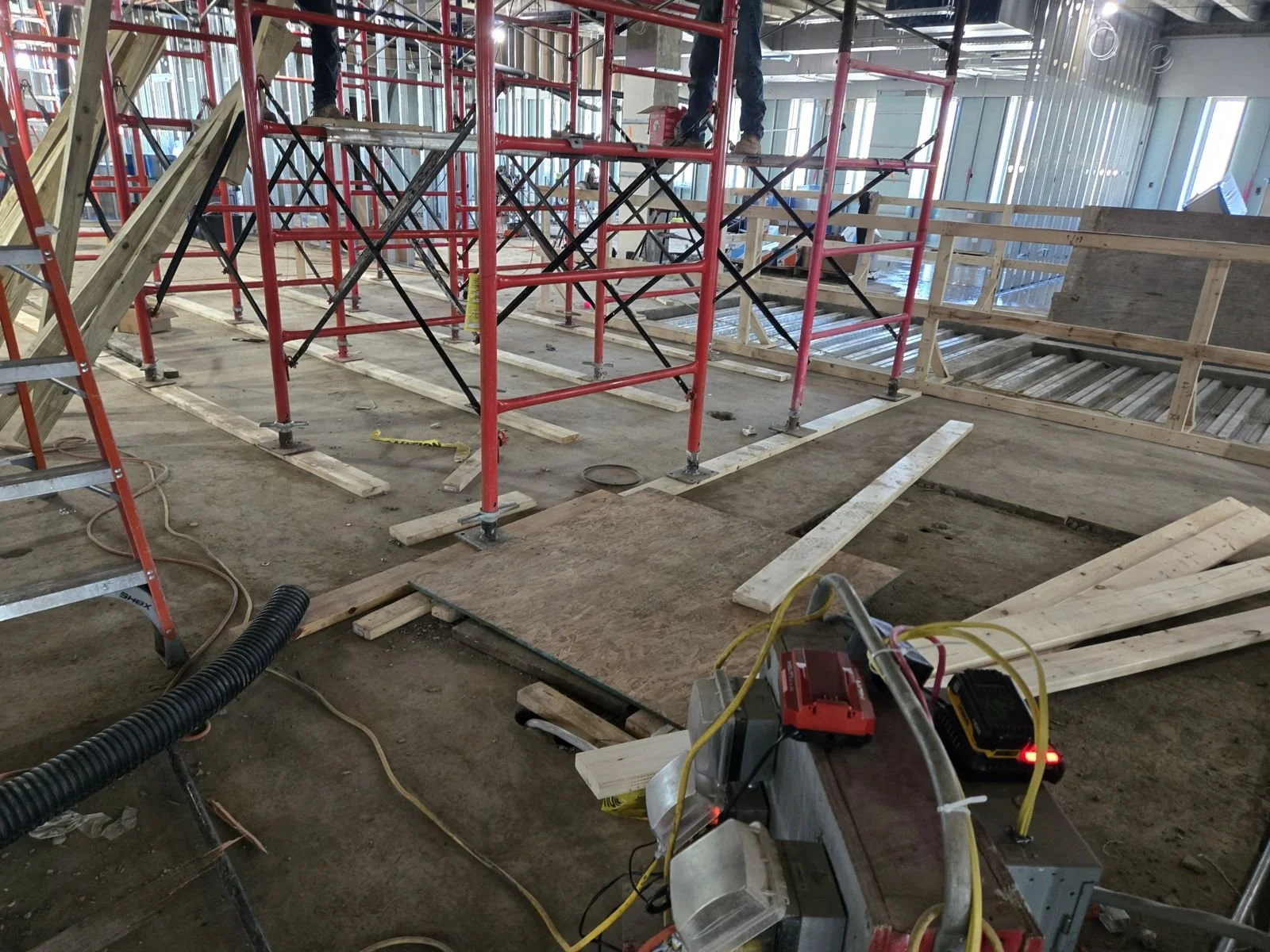
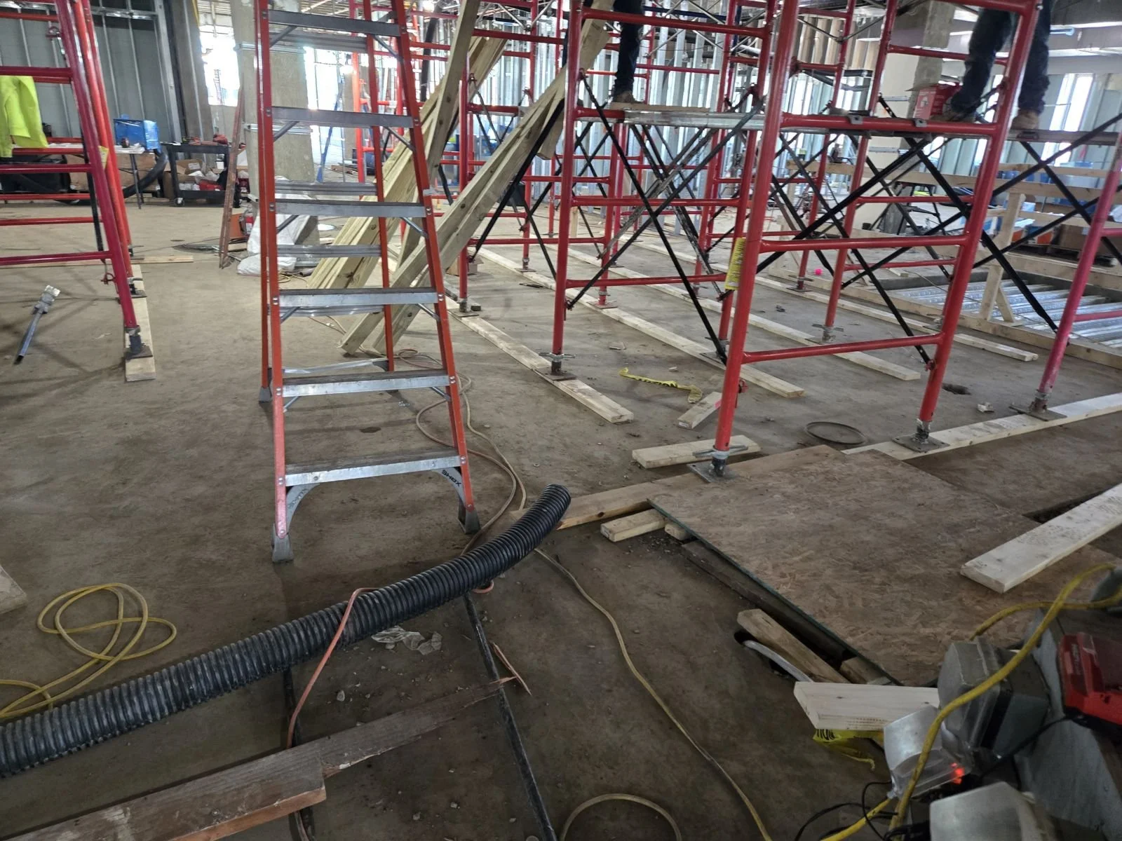
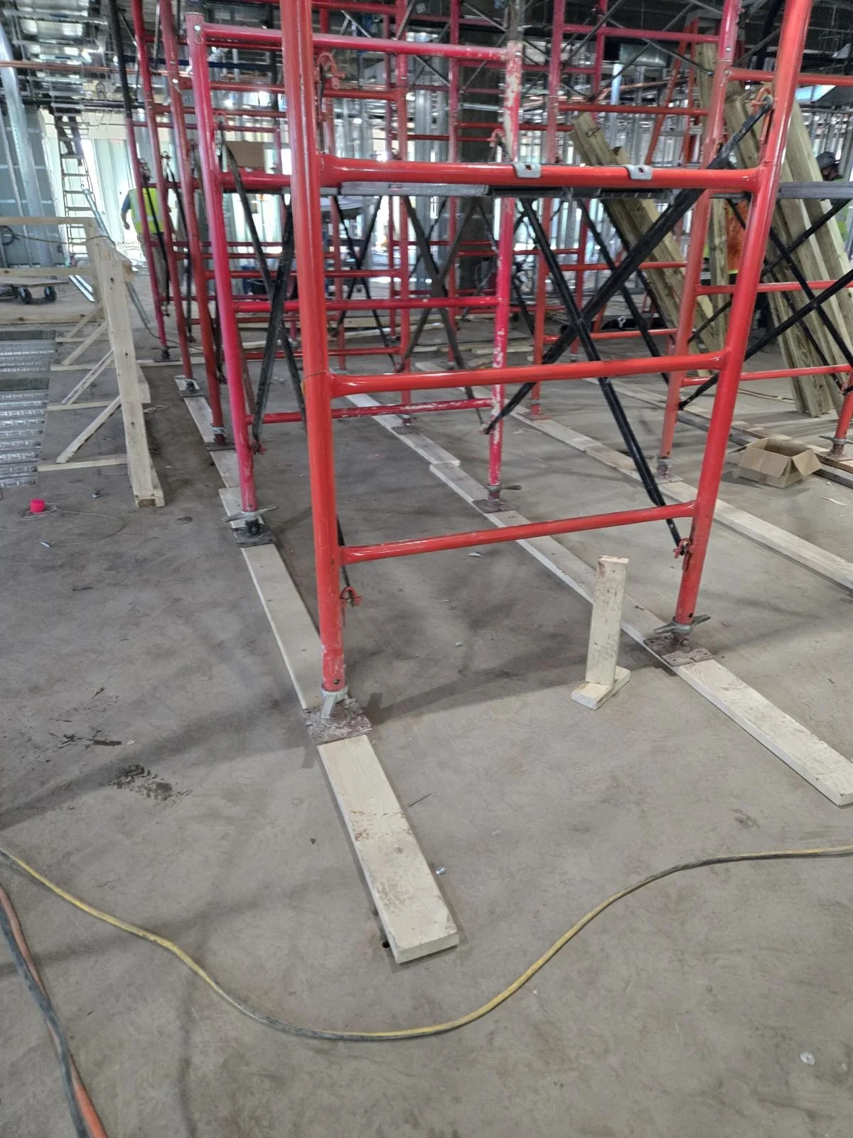
The planned load path used 3/4-inch plywood, SPF No. 1 2×6 framing members, 7.5-inch Aluma stringer beams, W10×19 steel headers, WACO Hi-Load shoring frames, and 2×8 mudsills. The supporting floor below is part of that load path too: reactions continue through the mudsills and into the structure beneath the shoring.

How the Load Gets Down

Steel headers and stringer beams collect loads from the supported floor and transfer them to the shoring frames. The frame legs bear on 2×8 mudsills, which distribute the reactions to the supporting floor system below.

The full load path—from the supported floor to the structure beneath the shoring—must be checked.
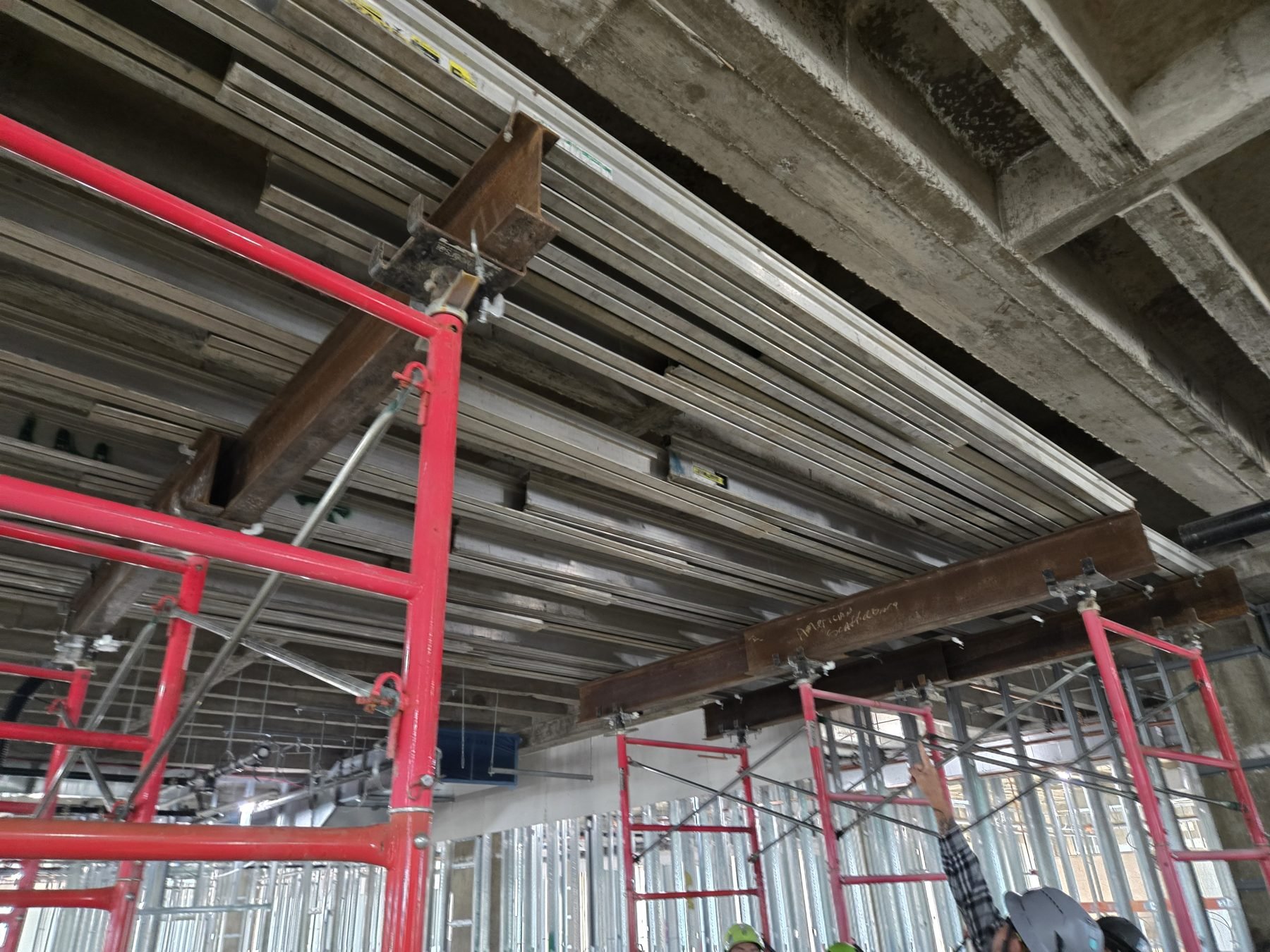
Load path: top to bottom
1Existing pan-deck + 3/4" plywoodPlywood spans the strong direction
2SPF No. 1 2x6 joists16" on center
37.5" Aluma stringer beams
4W10x19 steel headers
5WACO Hi-Load shoring frames2-tier, 4' x 6'
62x8 mudsills3' long, spreading the leg loads
7Supporting floor system below

Steel beams bearing on scaffold towers, carrying the remaining deck.

Designing for Two Conditions

Temporary shoring must account for changing loads as construction progresses. Each modeled opening was analyzed for two conditions:

  • Existing-joist demolition: the area being demolished, the tributary floor area remaining and temporarily supported, and construction live load.

  • New-beam placement: the proposed beam weight, the tributary floor area remaining and temporarily supported, and construction live load.

The calculated dead load was 100 psf. Adding a 50 psf construction live load resulted in a total floor load of 150 psf.

The proposed concrete beam loads were modeled as 117 plf for B-01, 333 plf for B-02, and 250 plf for B-03.

For the modeled framing, the maximum 2×6 center-to-center spacing was not controlling. The maximum calculated WACO frame-leg reaction was 7.3 kips for one condition and 6.4 kips for the other. Those reactions were below the 11.1-kip capacity used for the specified two-tier, 4-foot × 6-foot Hi-Load frame.

Interactive sketch: tap a layer to see what it is
OPENING
Existing deck. At the opening it is demolished; the deck that remains is temporarily supported.
3/4" plywood. Used in the strong direction. Safe spacing at 150 PSF is 21" c/c; 16" c/c was used.
SPF No. 1 2x6 joists at 16" on center.
7.5" Aluma stringer beams. Checked for moment, end reaction and deflection.
W10x19 steel headers. Steel beams that deliver the supported floor load into the shoring frames.
WACO Hi-Load frames. 2-tier, 4' x 6'. 11.1 kips available per leg.
2x8 mudsills. 3 ft long; about 260 sq in of bearing area against roughly 2 sq in required.
Supporting slab. The review flagged a 4" slab as insufficient for the post loads: shore to the slab on grade or add a spreader beam.

Coordination in the Field

The layout had to work with equipment that could actually be supplied and installed. The construction manager shared the Aluma beam lengths available on site, and SD&C coordinated with the shoring supplier on practical layout options. The geometry around some openings made the tower and beam arrangement more demanding, so supplier input helped connect the design layout to the equipment and field conditions.

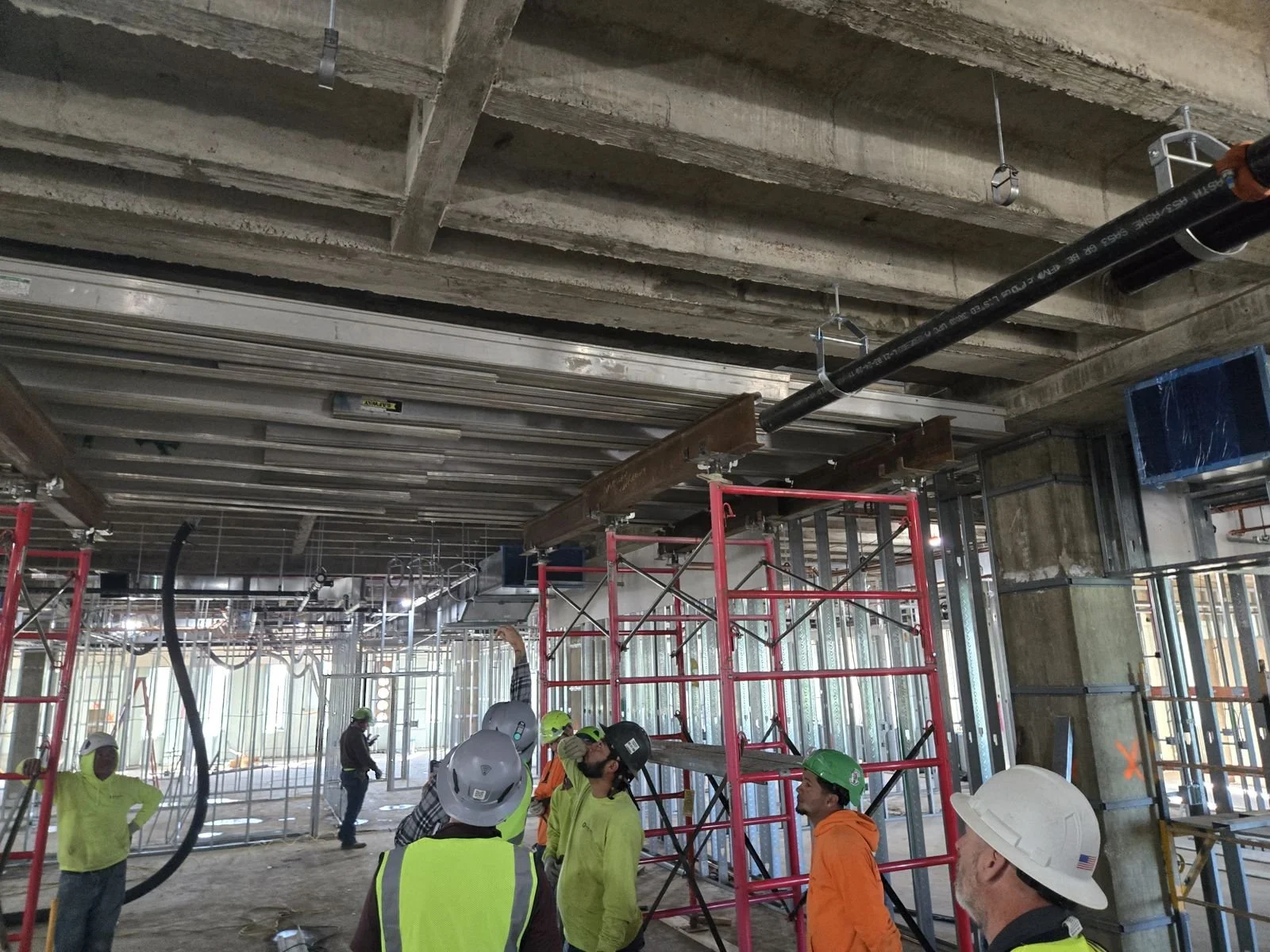
The design used staggered 12-foot Aluma beams through the center demolition area to provide support near the proposed openings. Before slab cutting began, SD&C visited the site with the project team to review the installed arrangement and discuss how the projecting beam ends would remain restrained as demolition changed the support conditions.

The team discussed two practical approaches: capture a projecting beam against an adjacent beam, or reposition it so it remained supported at the required header locations. The discussion kept attention on the installation details, span limits, and connections needed for the intended arrangement.

A Sequence the Trades Could Work With - The planned sequence gave each trade a clear handoff:
1. Install shoring at two floors. SD&C was brought in to review the installed arrangement before slab demolition.
2. Saw-cut and remove the concrete joists at the openings. The cut pan deck joists then rest on the shoring towers.
3. Form and cast the new concrete beams. Allow the beams to cure before moving the shoring to the next floors.
Know the full load pathConcrete deck, shoring, then the supporting slab or foundation.
Design for construction loadsWorkers, material handling, equipment, debris and removal sequence all matter.
Think about the next tradeShoring must support today's work without blocking tomorrow's.
Planning the work in stages helped the project team coordinate demolition, concrete placement, equipment availability, and access for the crews working below.

The Value of Working Together

Temporary support sits at the intersection of design and construction. The engineer checks the loads and support arrangement. The general contractor coordinates the overall sequence. The shoring supplier brings equipment knowledge and availability. The demolition and concrete crews understand how the work will be installed and what access they need.

When those perspectives come together early, the team can work through constraints before they interrupt the sequence. That was the value of keeping SD&C involved from demolition through concrete placement: one coordinated view of the temporary support across both phases.

The Takeaway

Complex site work depends on more than a good drawing. It depends on communication among the people designing, supplying, installing, and building the work. Coordinating the shoring across demolition and concrete phases helped the project team plan each step around the conditions on site and the work that followed.

If your project involves structural openings, demolition, or temporary support within an active construction site, SD&C can help coordinate the engineering with equipment and field sequencing.

#TemporaryWorks #Shoring #ConstructionEngineering #StructuralEngineering #ElevatorModernization #WACOScaffolding