
The ‘Hybrid’ Fix for Bowing Basement Walls
Location: Westerville, OH | Challenge: Hydrostatic Pressure & Wall Shear | Solution: CFRP + Helical Tie-backs
Basement walls are constantly fighting a battle against the earth outside them. In our recent project at Westerville, OH, we encountered a textbook case of "Hydrostatic Pressure" winning that battle, until we intervened.
This blog (mini case study) breaks down the engineering behind a bowing 8-inch CMU (concrete masonry unit) wall and the hybrid reinforcement system we designed to stabilize it. We will explore why we moved beyond standard repairs to combine Carbon Fiber Reinforced Polymer (CFRP) with Helical Tie-backs.
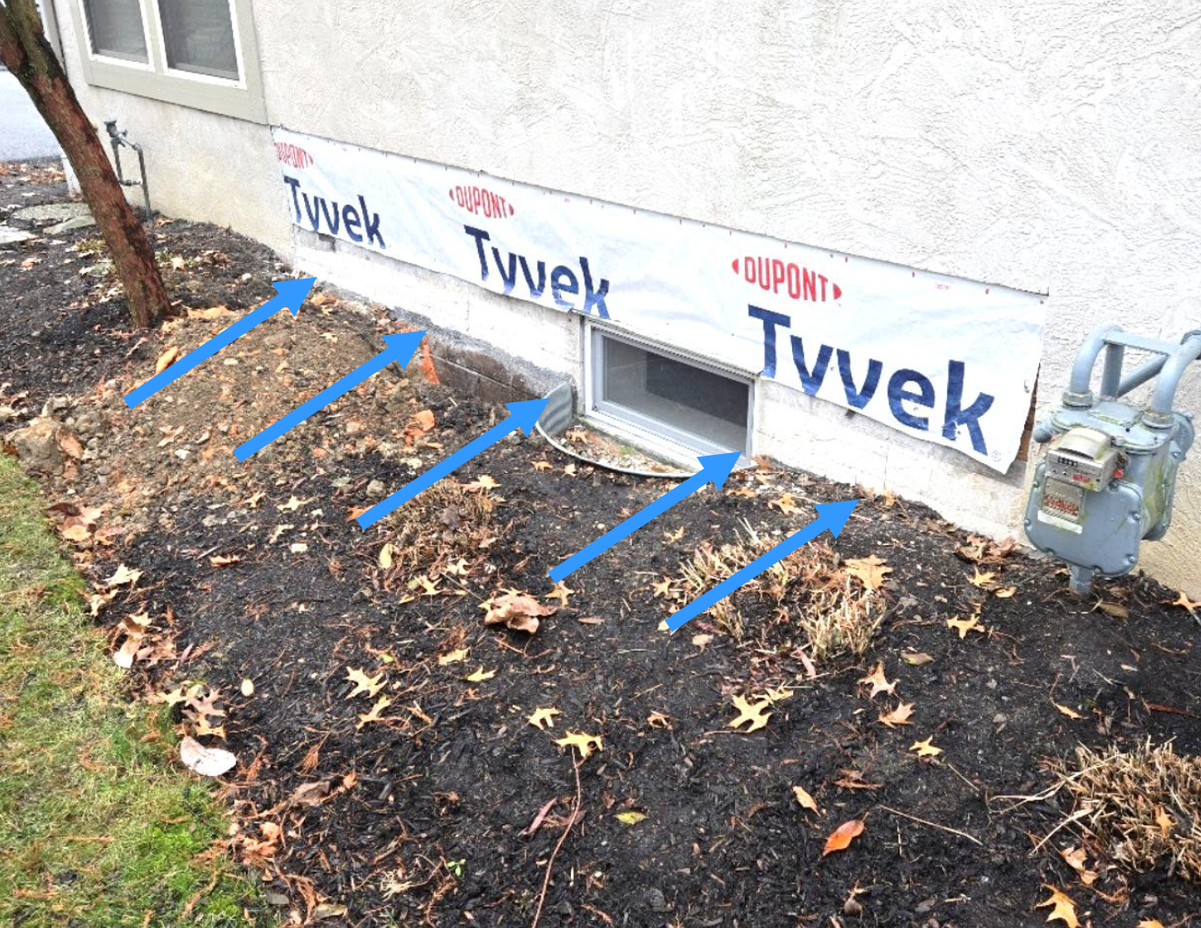
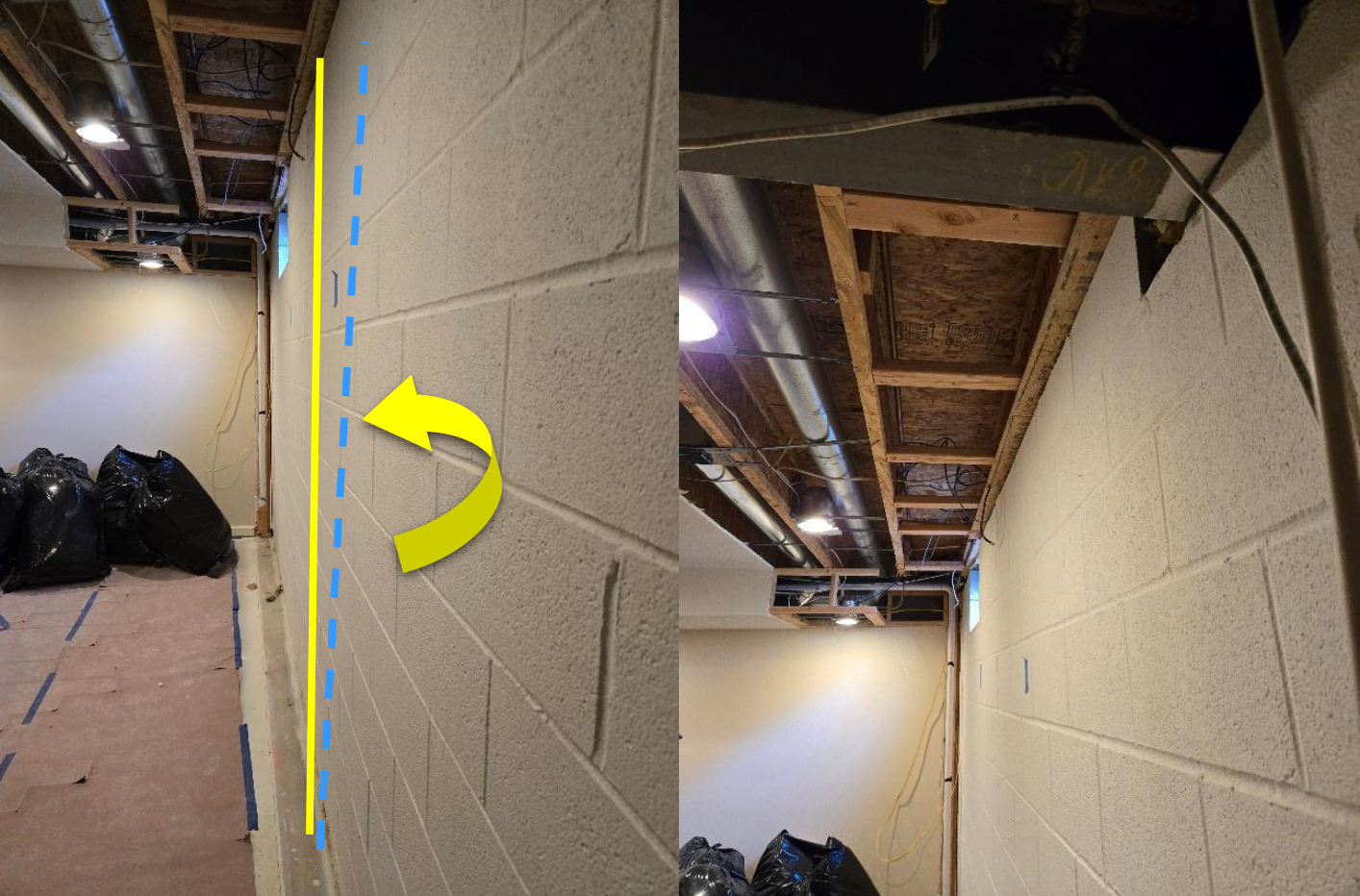
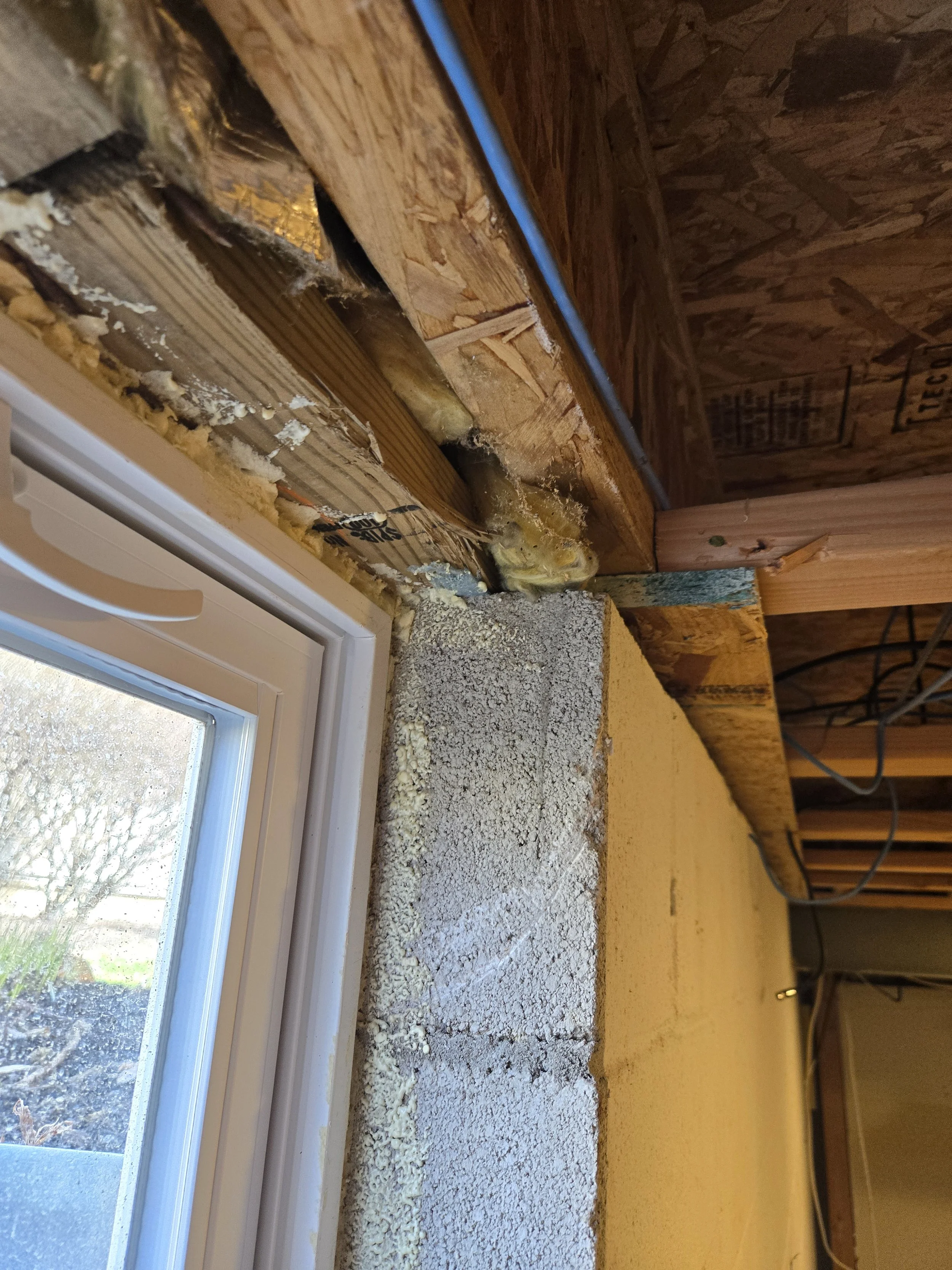
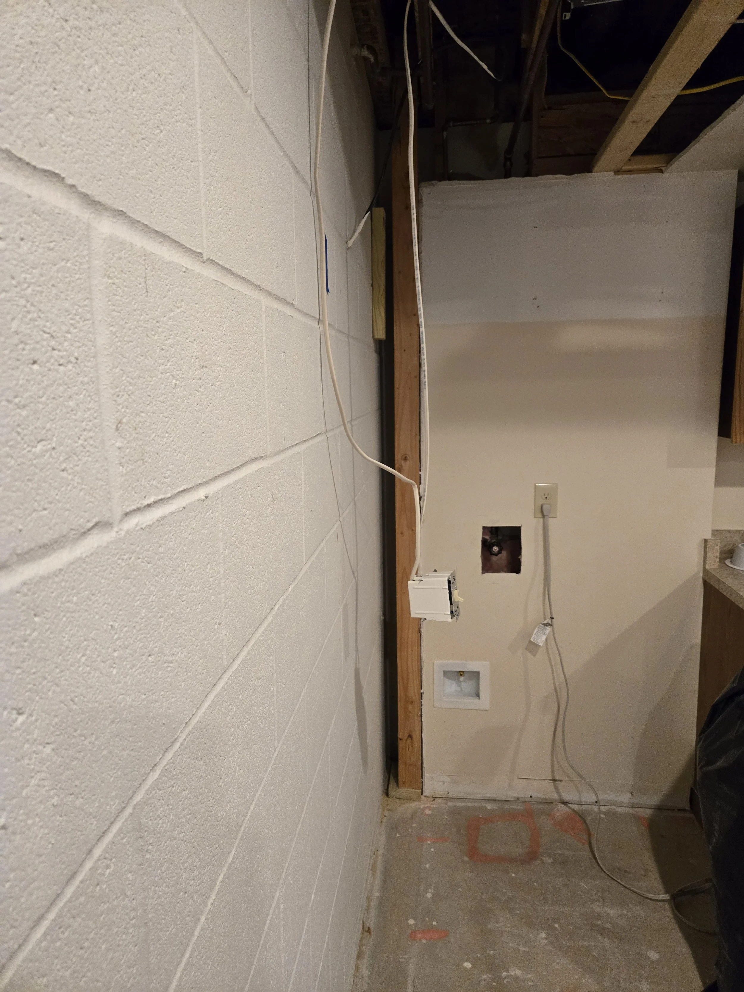
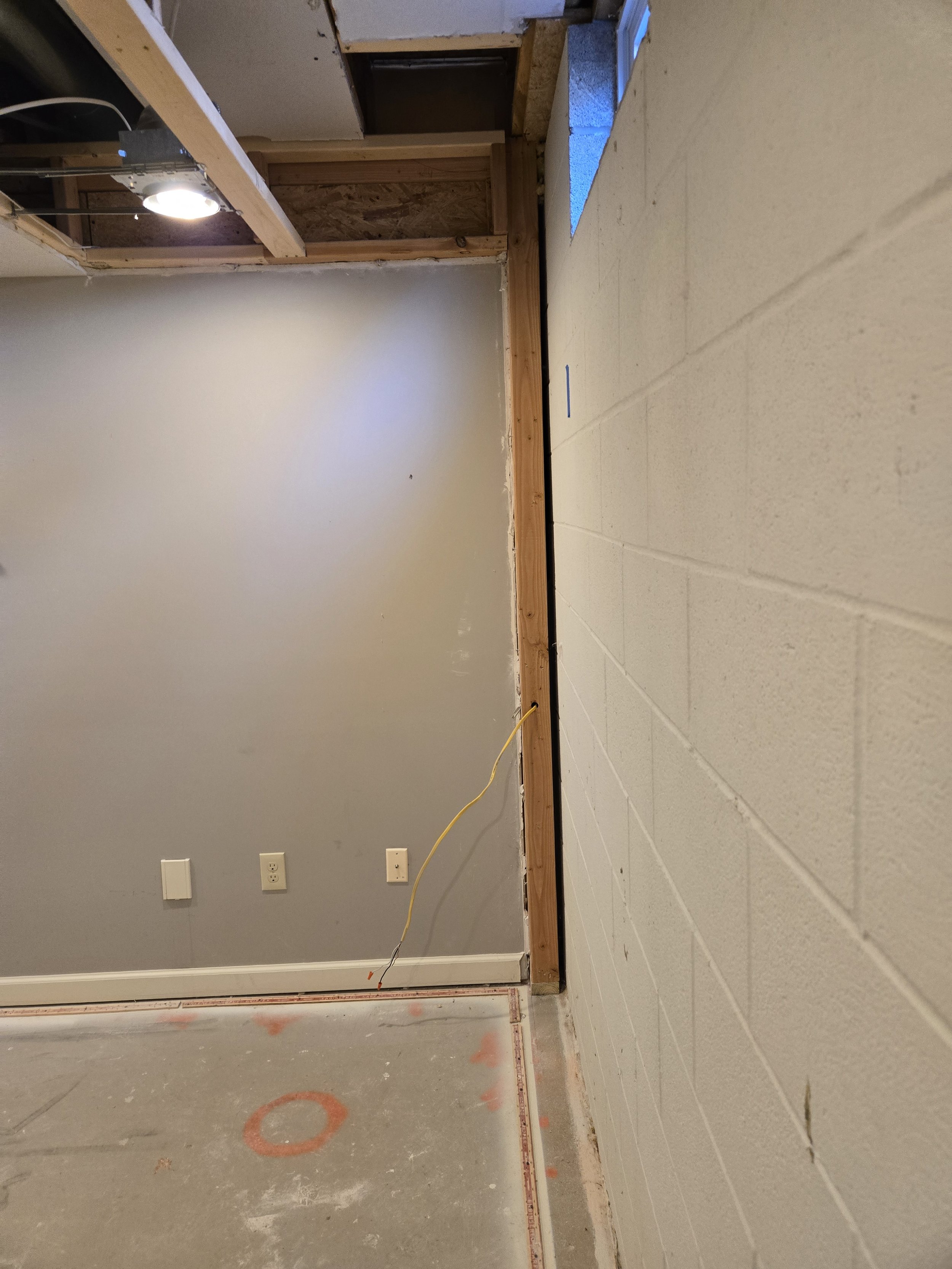
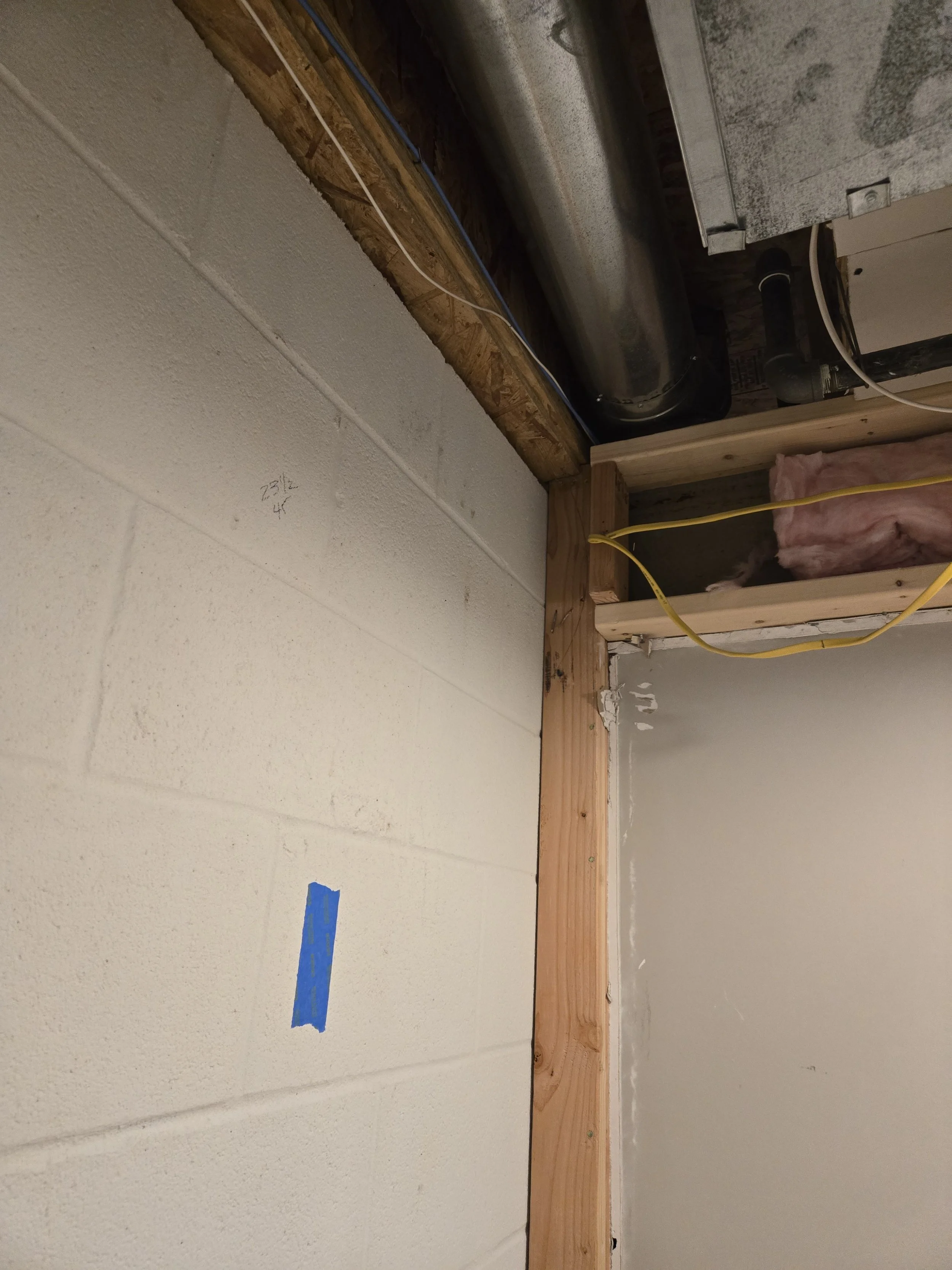
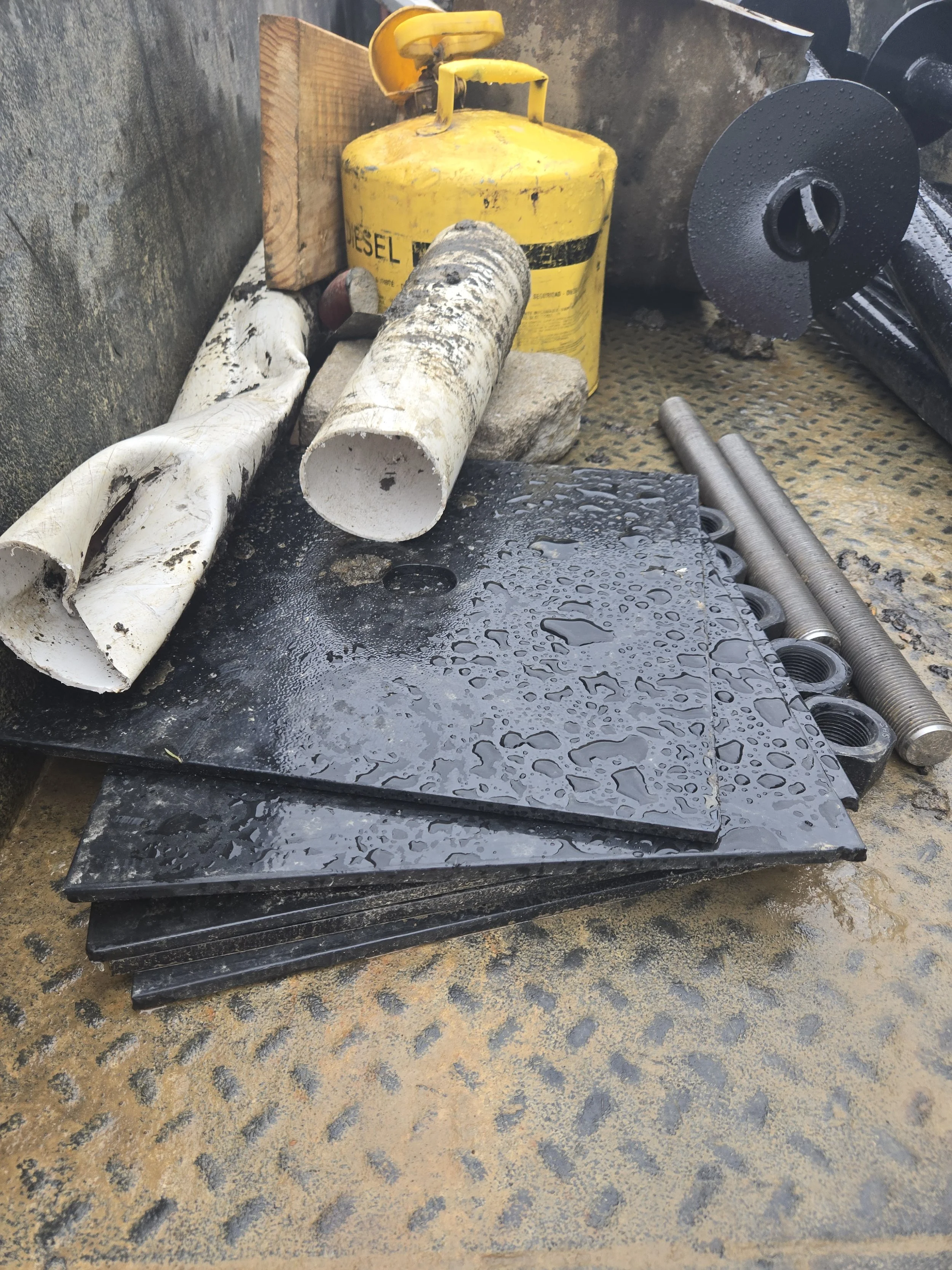
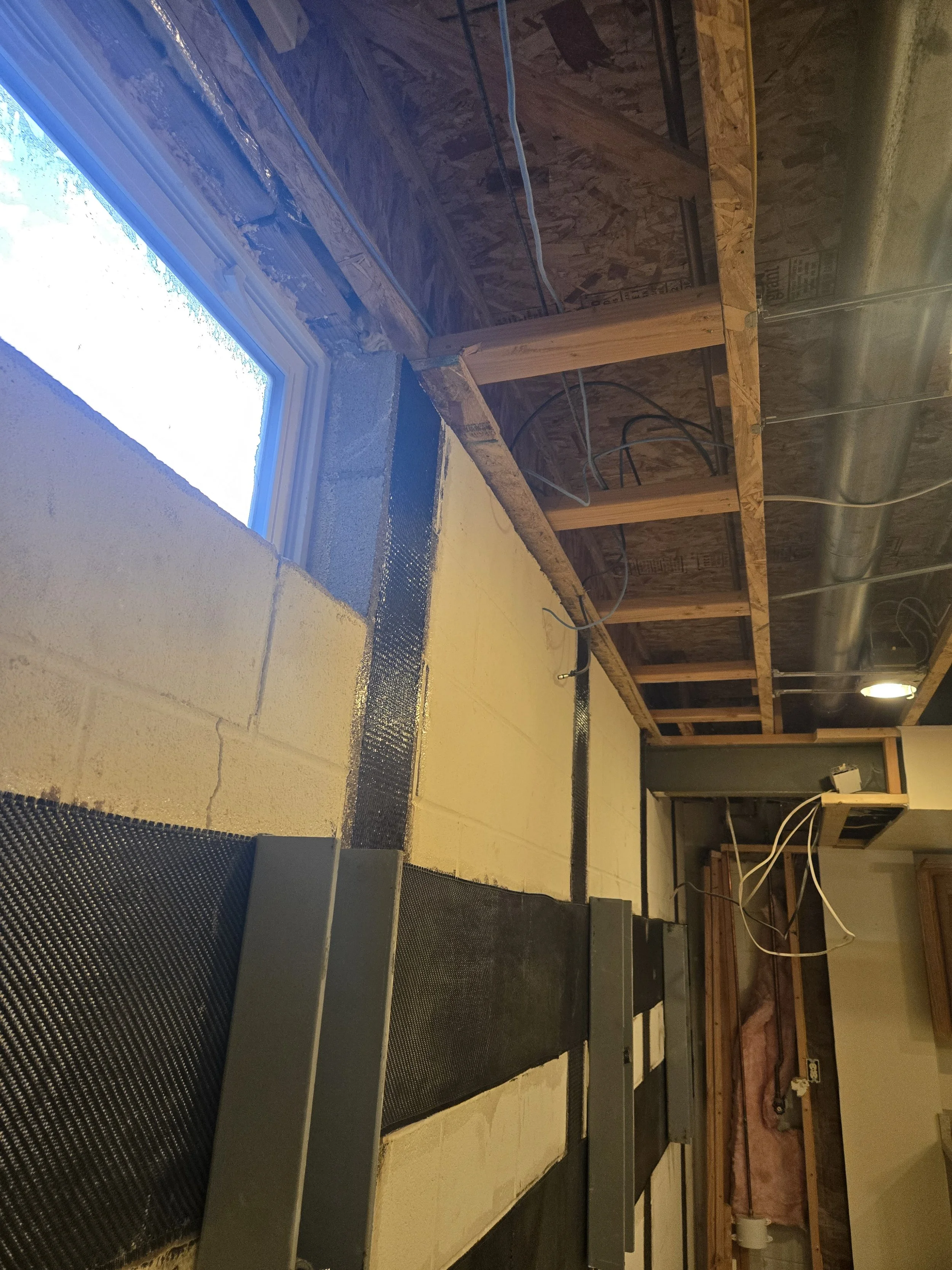
Initial Site Photos
1. The Physics of the Problem: Why Walls Bow
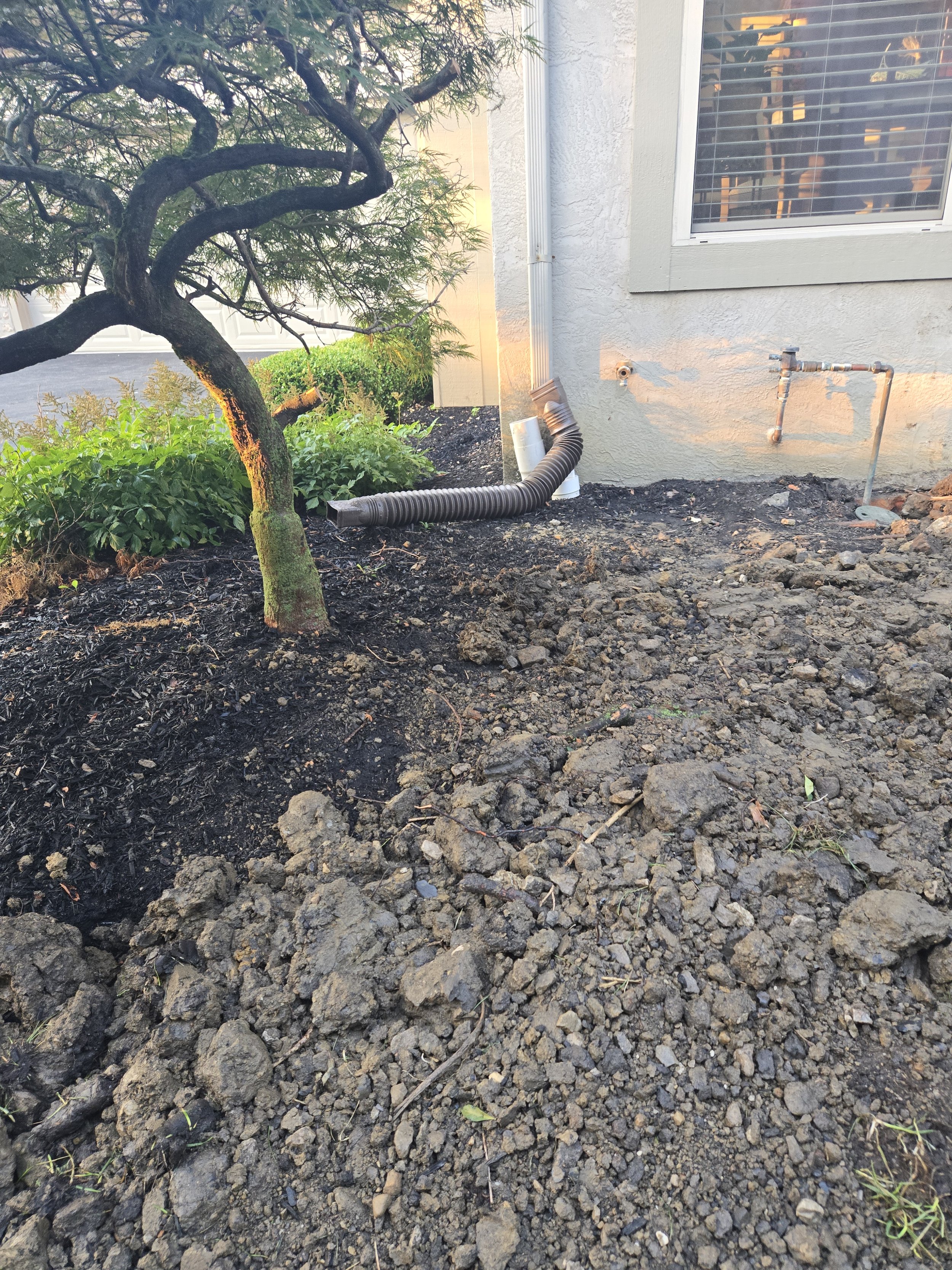
The primary culprit in this case wasn't just age; it was water. The inspection revealed that the exterior grading was trapping water near the foundation, and downspouts were terminating too close to the home.
When soil becomes saturated, it gets heavier and acts like a liquid, exerting Hydrostatic Pressure. This creates a triangular load distribution: zero pressure at the surface, increasing linearly to maximum pressure at the footing.
Interactive: Visualize the Forces
Use the slider below to see how soil saturation changes the force profile on a basement wall.
In our case, the wall was bowing inward by approximately (leaning) about 1 degree. While this sounds small, masonry has very low tensile strength, it cracks easily when bent.
2. The Solution: A Hybrid Reinforcement System
Standard repairs often use either steel beams or carbon fiber. For this project, we engineered a hybrid approach to address two distinct forces:
Bending (Moment): Addressed by vertical Carbon Fiber straps.
Shear (Sliding): Addressed by Helical Tie-backs and Horizontal straps.
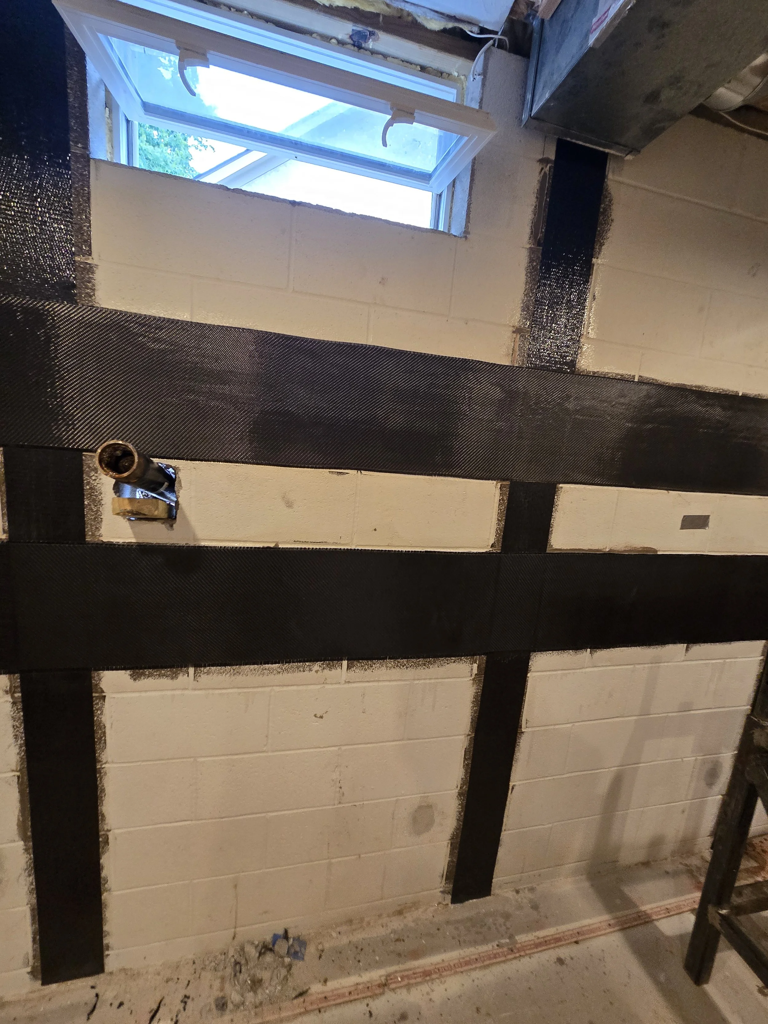
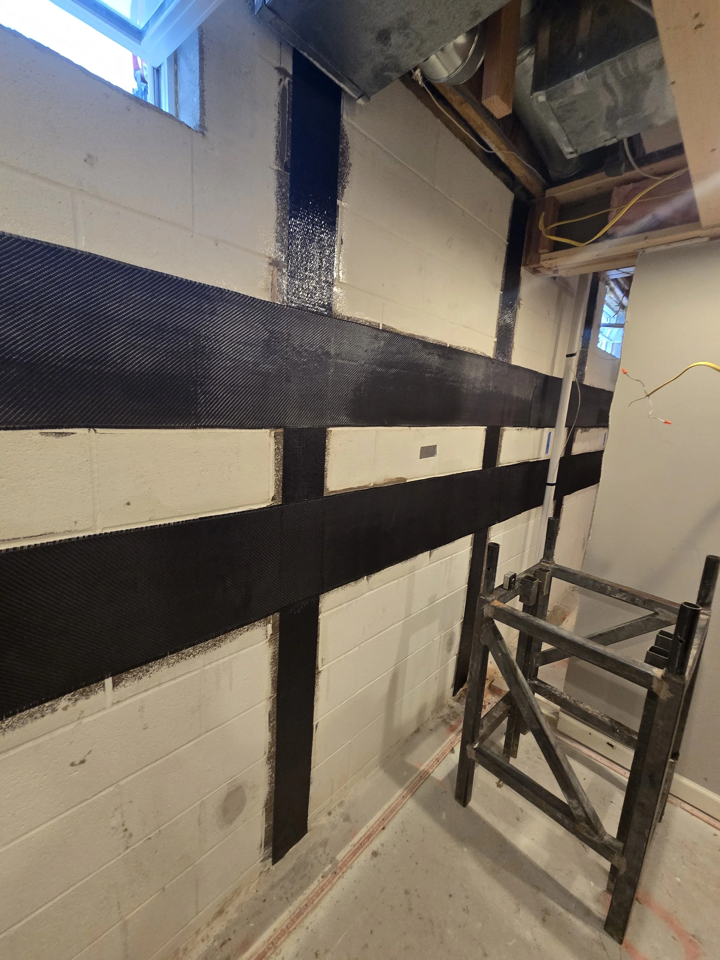
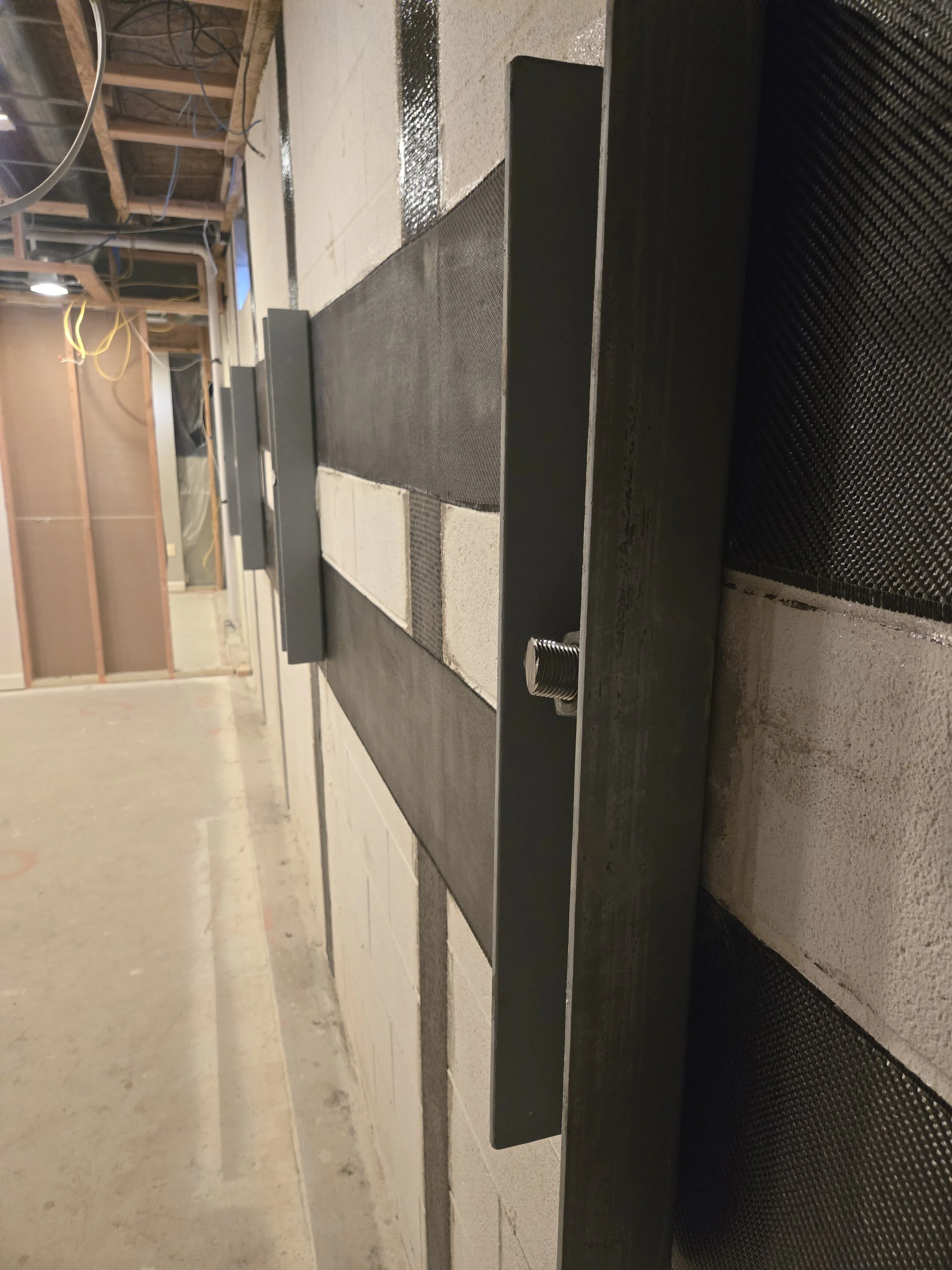
● Step 1: Vertical CFRP (The "Spine")
These straps behave like external rebar with very high tensile stiffness. Carbon fiber has very low elongation prior to failure, so it does not significantly stretch under service loads. Instead, the CFRP takes tensile load and prevents the masonry from separating — when the wall tries to bow inward the CFRP restrains the interior mortar joints from opening, keeping the block wythes acting together.
Bonding: Epoxy-bonded directly to the masonry to form a composite shell.
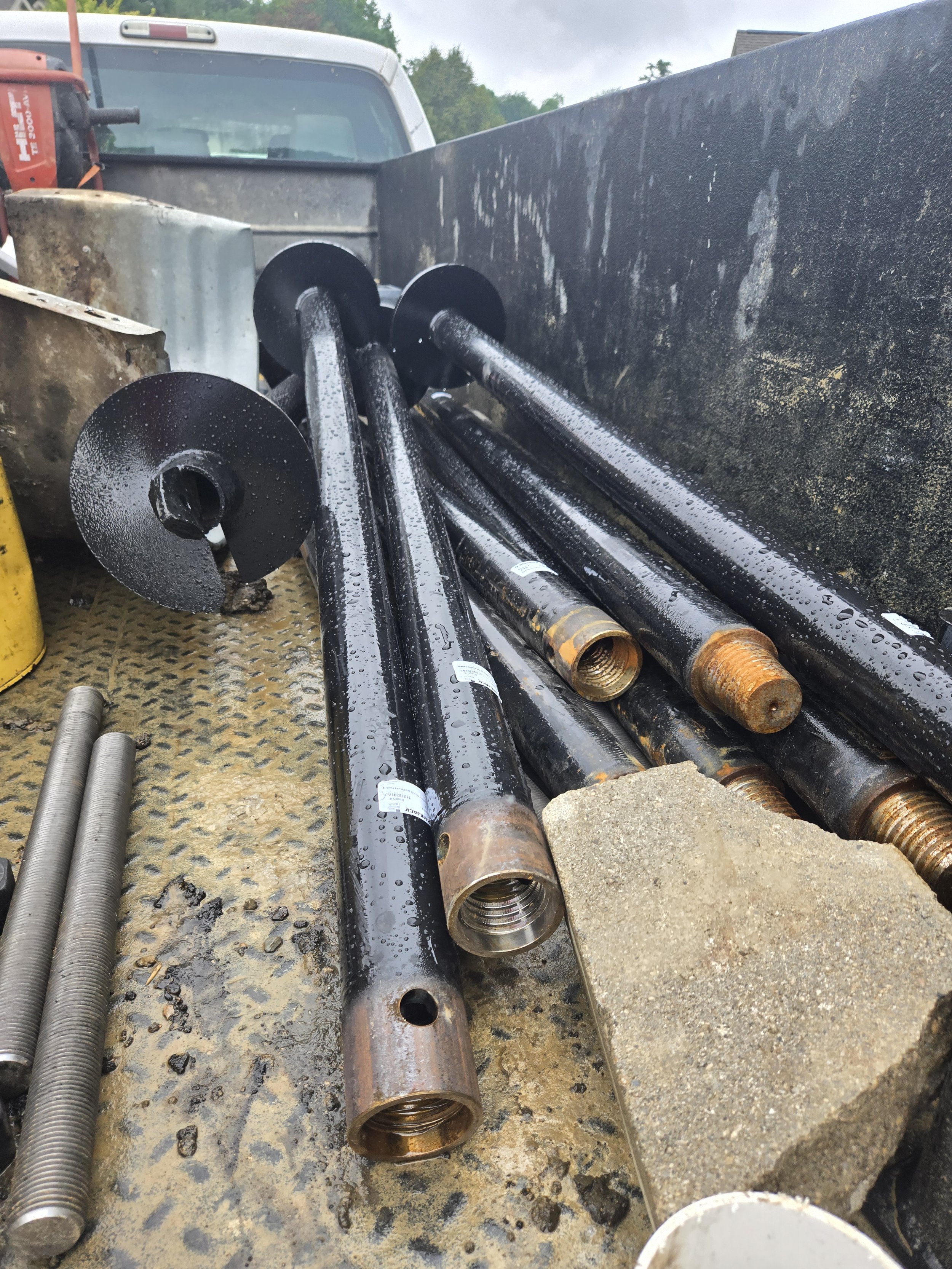
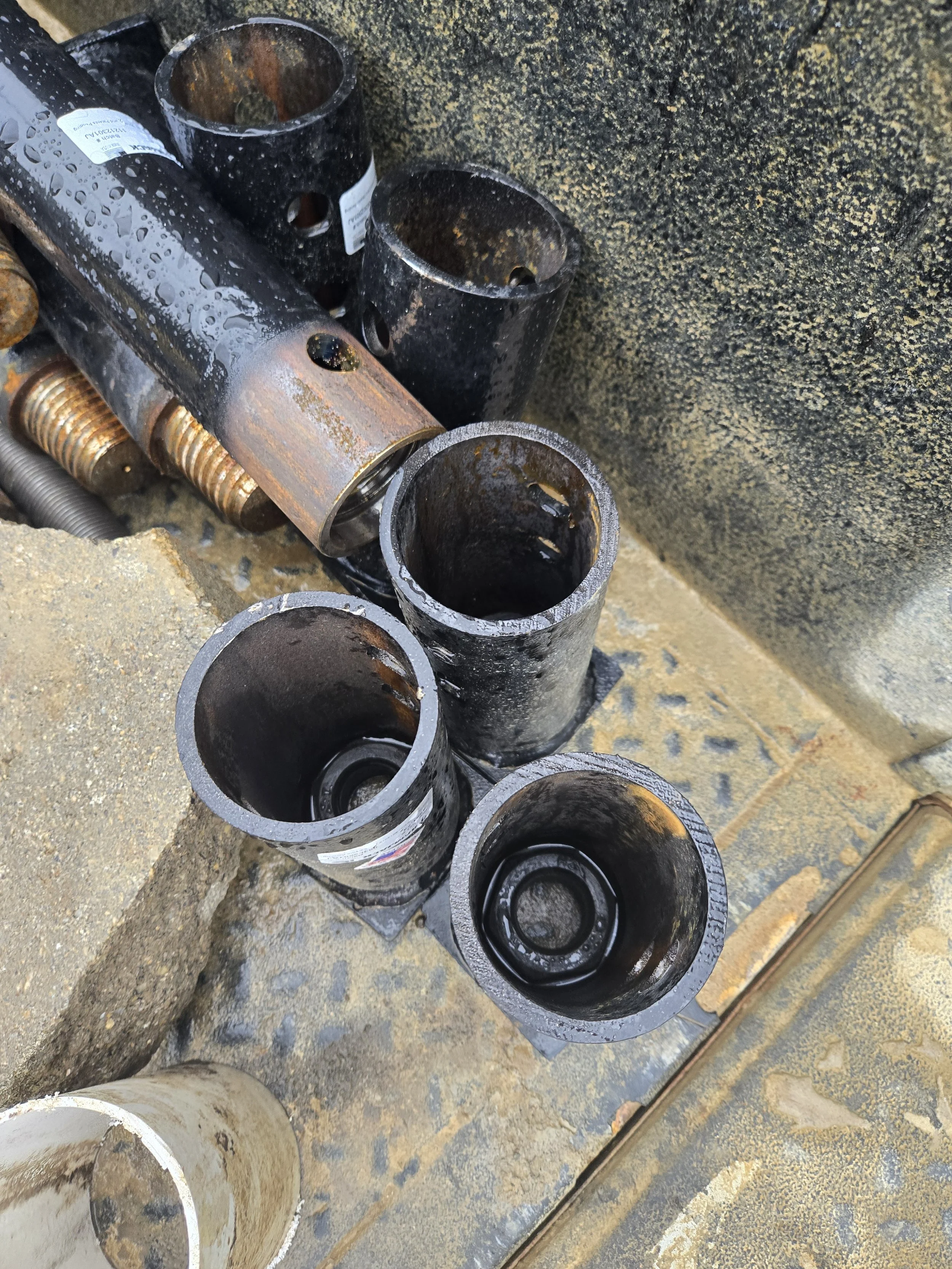
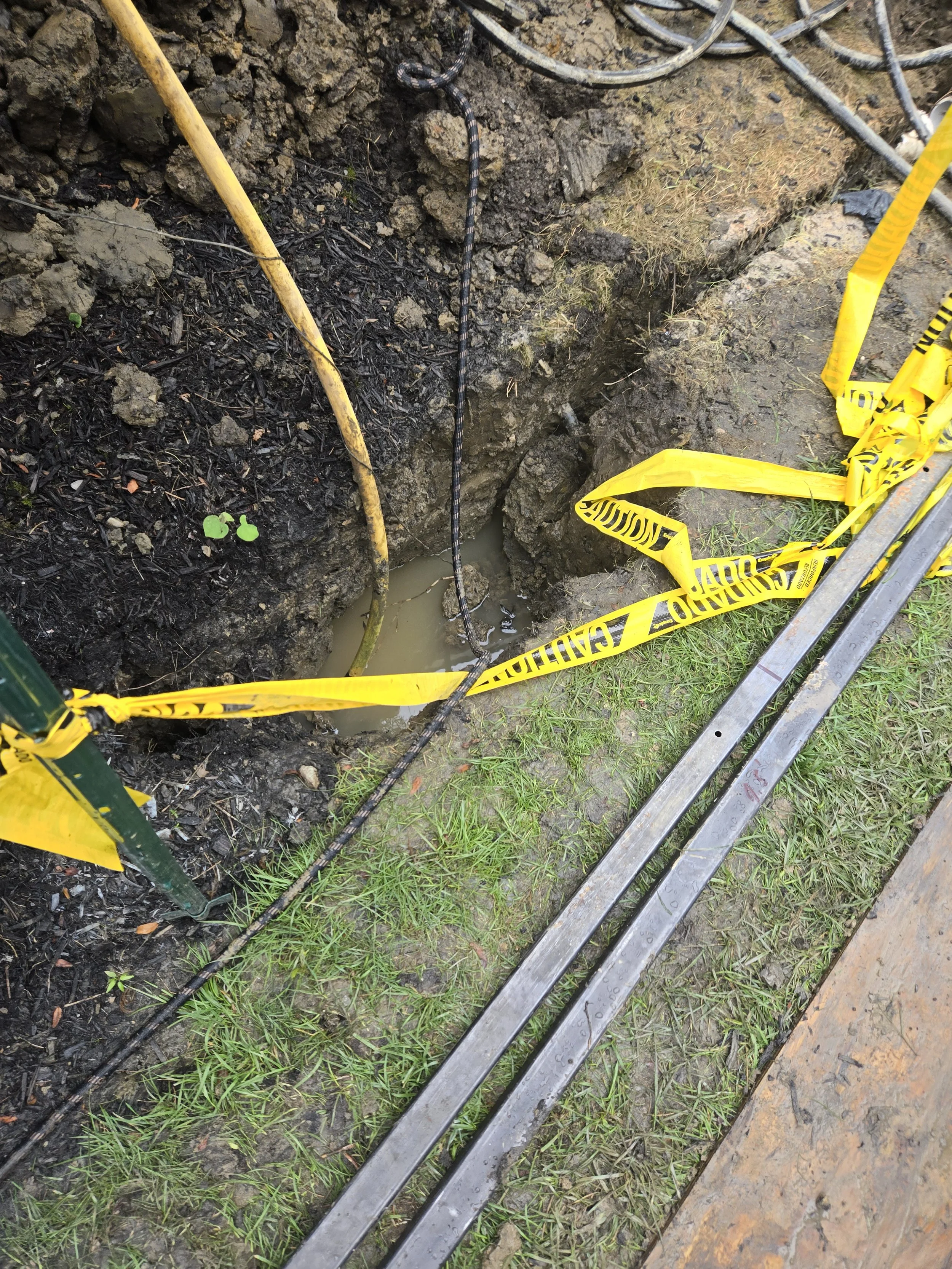
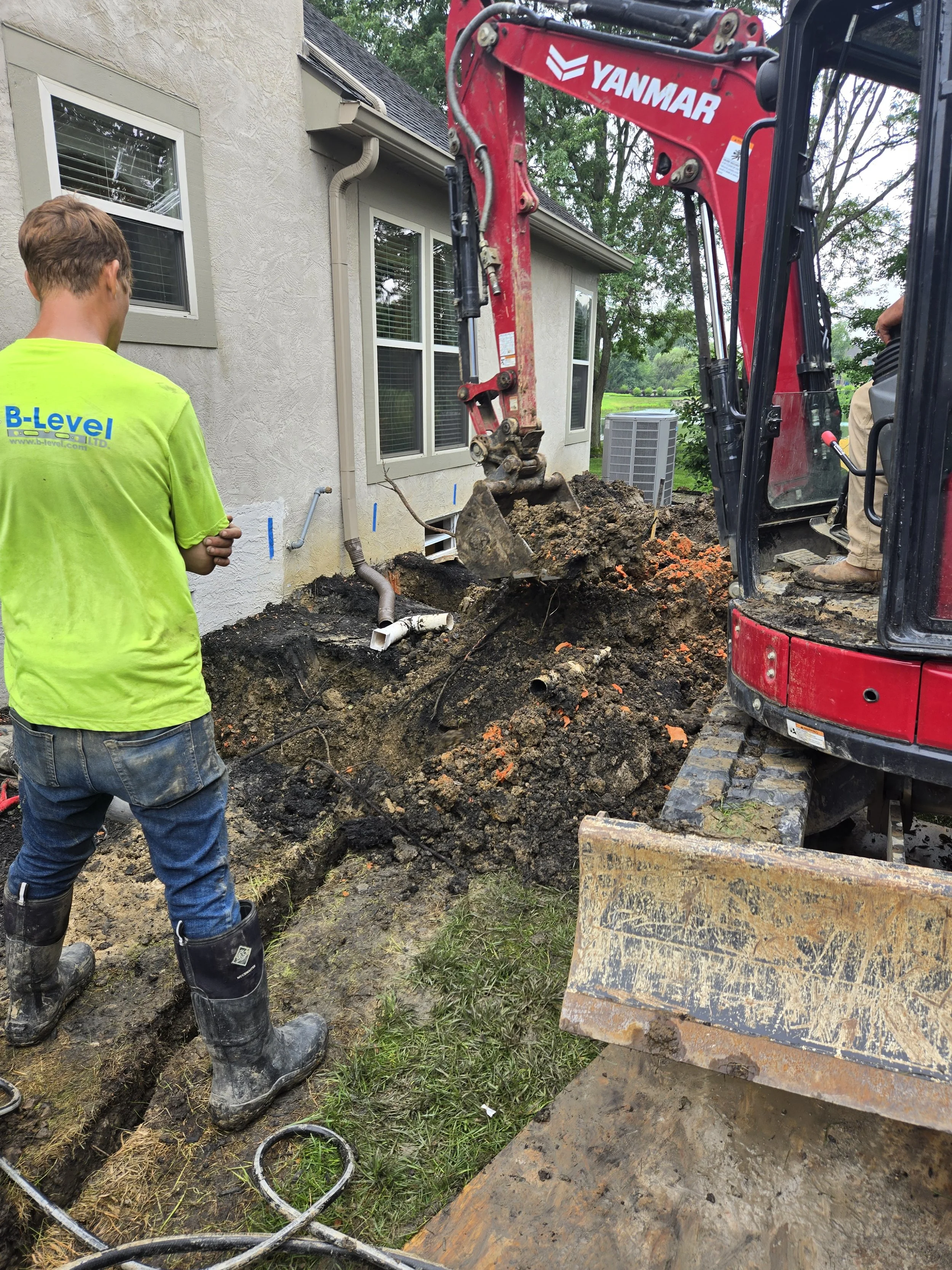
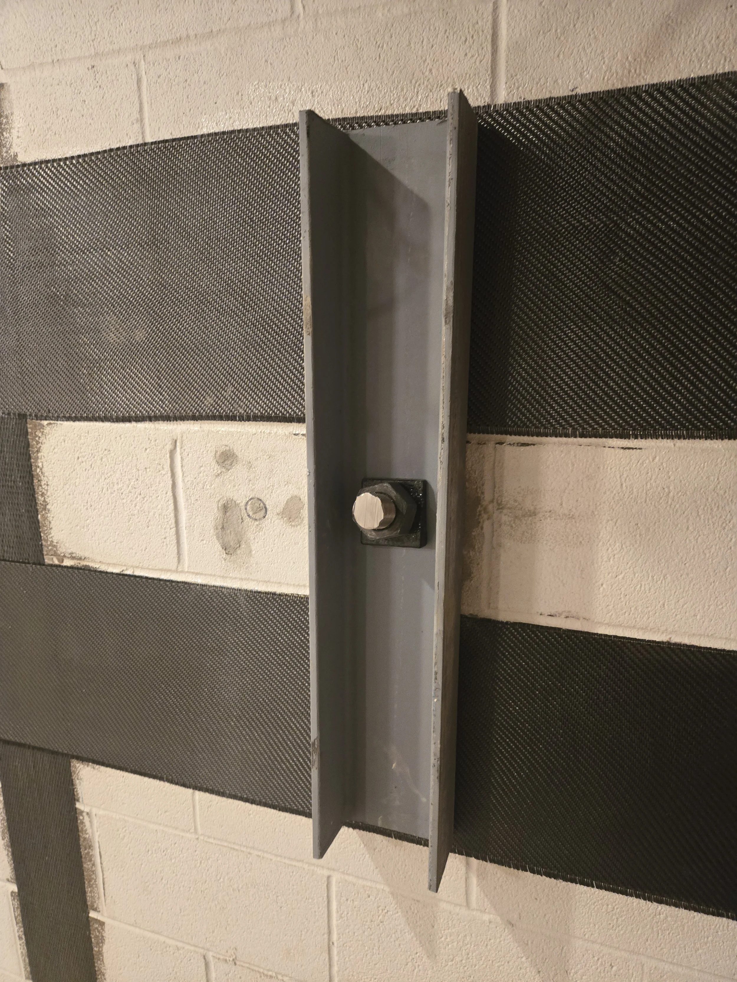
● Step 2: Helical Tie-Backs (The "Anchor")
In addition to providing resistance to sliding (shear), the tie-backs also restrain the top of the wall against overturning. We installed Ramjack helical tie-back anchors driven ~16 ft into competent soil at about a 15° angle. Each anchor is rated at approximately 20 kips (20,000 lb) of tension and transfers load into deeper soil strata. (20Kip is almost equal to weight of 🚌-🚌 two small schools buses)
● Step 3: Horizontal Distribution (The "Waler")
Team applied 12" SRS-660 bidirectional carbon fiber as a continuous composite waler. This horizontal layer distributes the point-load from each steel anchor across the wall and provides secure anchorage for the tops of the vertical CFRP straps, preventing local punching or concentrated bearing at the anchor locations.
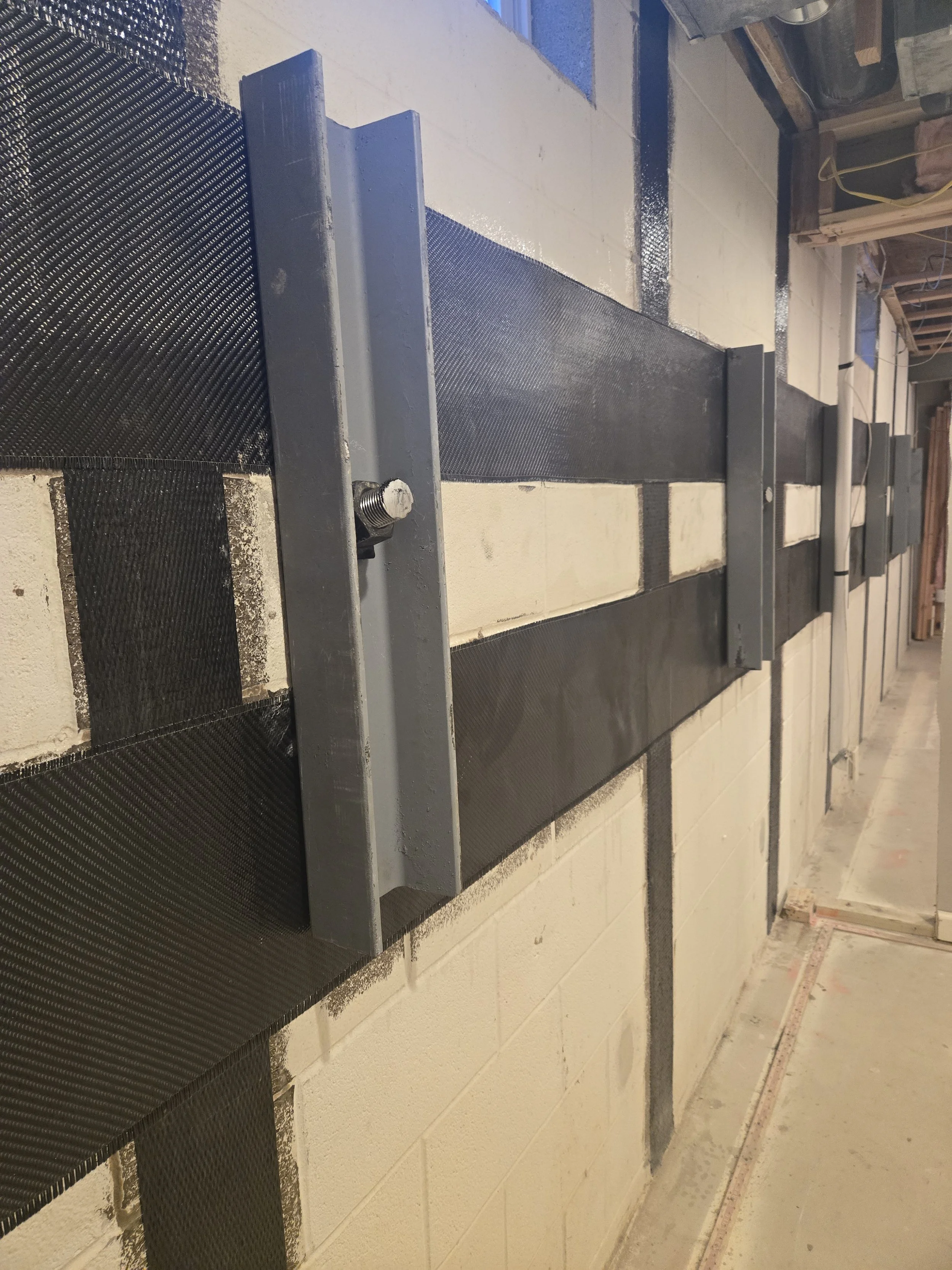
3. Anatomy of the Repair
Understanding how these layers work together is crucial. Explore the diagram below to see the build-up of the repair system.
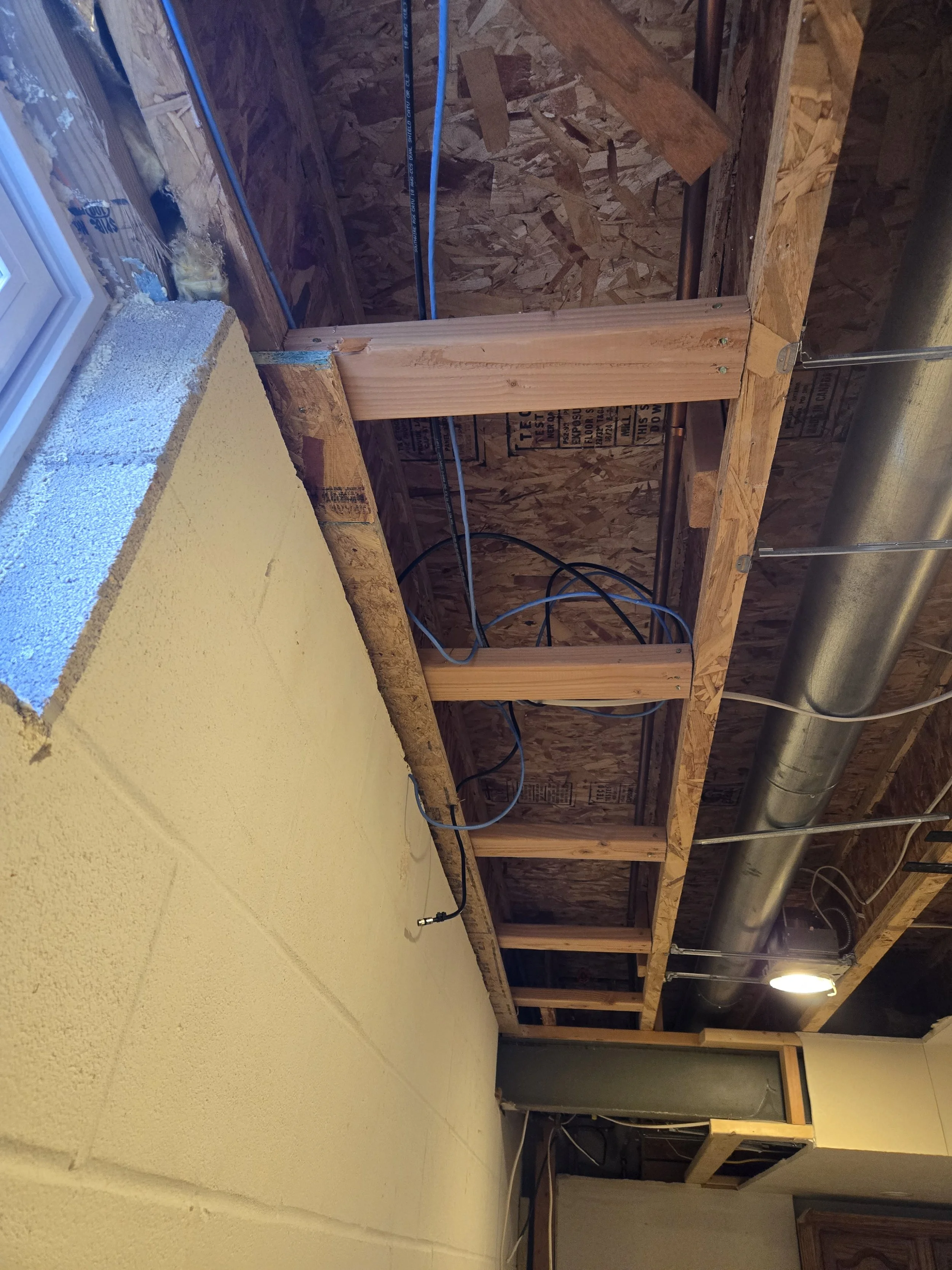
Site Photos: During Process of Repair
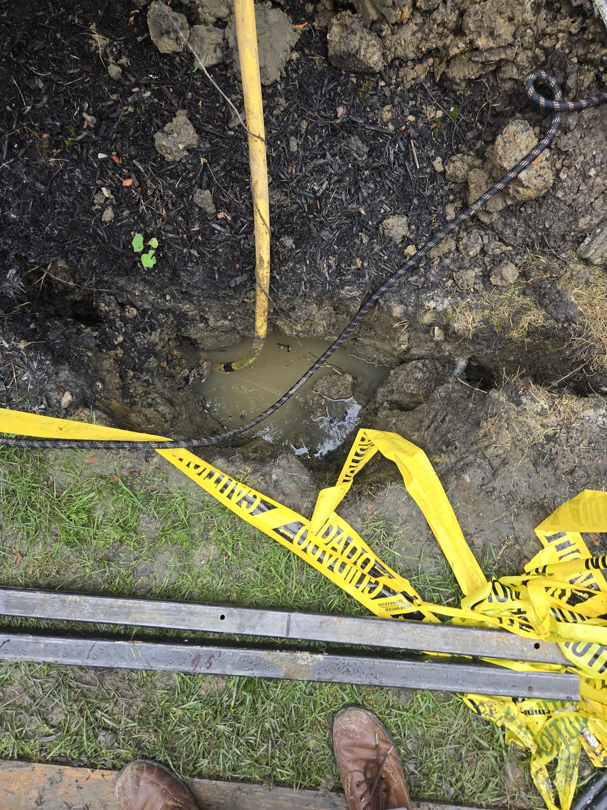
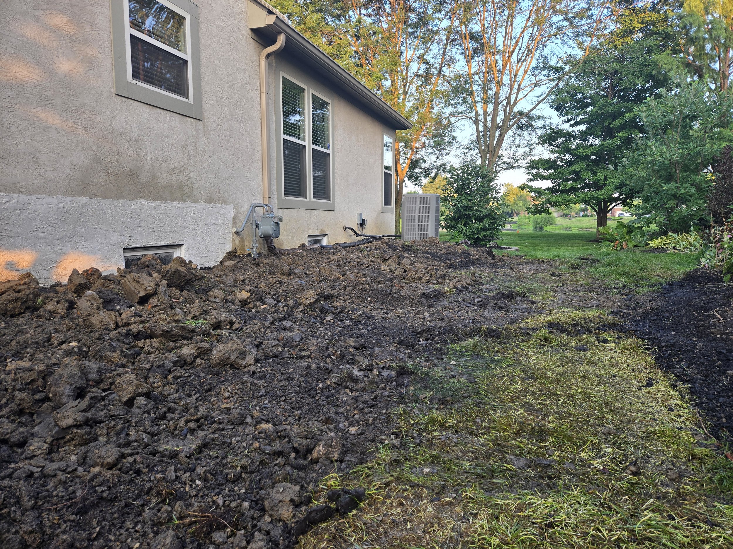
4. Final Verification and Drainage
Structural repair is only half the battle. If we don't fix the source of the water, the pressure returns.
Grading: We recommended adjusting the exterior soil to maintain a 1" drop over the first 12" (8.33% slope) away from the foundation.
Downspouts: The inspection identified downspout drains that needed to be buried and extended 10-20 feet away from the home to prevent water from pooling against the newly repaired wall.
Site Photos: After Repairing
The Result
The final inspection, conducted in August 2025, confirmed the repairs were satisfactory. By combining the high-tech tensile strength of carbon fiber with the brute force anchoring of helical piles, this basement wall has been transformed from a structural liability into a reinforced retaining system capable of withstanding soil pressures for decades to come.